
Pipe cutter

A technology for cutting knives, pipes

Inactive Publication Date: 2005-03-16
EMERSON ELECTRIC CO
View PDF6 Cites 0 Cited by
  • Summary
  • Abstract
  • Description
  • Claims
  • Application Information

AI Technical Summary

Problems solved by technology

Dust and environmental contamination can also adversely affect cutting operations
In fact, in some cases, dust and dirt in the sliding mechanism between the two supports made it impossible for this type of knives to work
It is difficult for a threaded shaft to overcome irregularities in the sliding mechanism, since the claw must be moved by an intermediate spring
The second stand is capable of moving into the cutting position, but during the cutting operation, the second stand may jump, jam, or affect the smoothness and reproducibility of the cut
Irregular friction causes runout, which may affect the uniformity of the tube cut
All of these disadvantages have led some operators to prefer the fixed bracket solution shown in US-A-5,903,980
Therefore, various self-feed pipe cutting knives are either special-sized, or not easy to achieve the best cutting state, or both

Method used


Image

  • Pipe cutter
  • Pipe cutter
  • Pipe cutter

Examples


Embodiment Construction

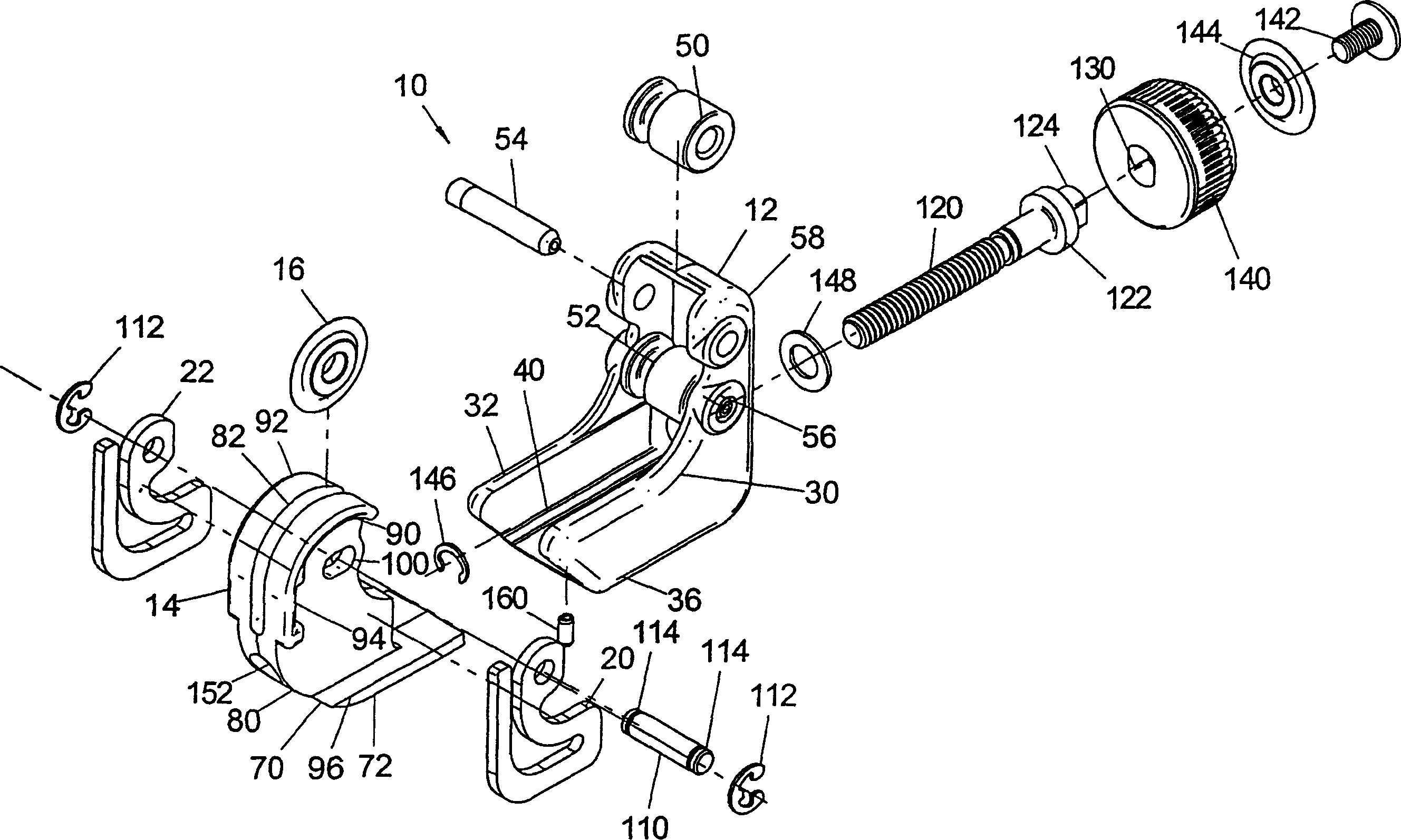
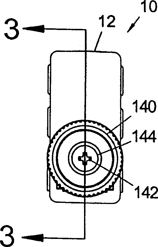
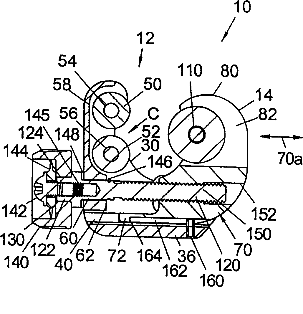
[0027] Referring now to the accompanying drawings, the contents shown in the drawings are only for illustrating the embodiments of the present invention, but not for limiting the present invention. Figure 1 to Figure 5 Represents a pipe cutting tool 10 having a first seat or bracket 12, and a second seat or head 14, such as Figure 4 and Figure 5 As clearly shown, a cutter head 16 for cutting the tube T is rotatably mounted on the cutter head 14 . During the cutting operation, the cutter 10 is loaded and rotated on the pipe either manually or by an electrically driven handle. During rotation, if Figure 6 Two spaced apart resilient elements 20, 22 in the form of leaf springs are shown to automatically advance the cutter head 16 towards the pipe. In operation, the second seat slides relative to the first seat until the cutter head 16 bears against the tube T. As shown in FIG. Further movement of the second support then deforms the springs 20, 22 until the springs are full...


PUM


Abstract

A tube cutter for cutting a circular tube having a central tube axis, the cutter comprising: a housing with first and second parallel rollers defining a cradle for receiving a tube cut with the tube axis generally parallel to the axes of the rollers, a cutter head reciprocally mounted on the housing for sliding linearly in a direction toward and away from the rollers, the cutter head having a base and an upstanding arm supporting a cutter wheel rotatable about an axis generally parallel to the axes of the rollers and facing the tube in the cradle, a spring element biasing the cutter wheel in the stated direction and toward the rollers, and a threaded shaft between the housing and cutter head, and rotatable to move the cutter head linearly toward the housing, whereby the cutter wheel engages the tube and the spring element creates a cutting force pushing the cutter wheel against the tube for cutting the tube.

Description

technical field [0001] The present invention relates to the field of pipe cutting, and more particularly, to a pipe cutting tool that feeds automatically while rotating to cut the pipe. Background technique [0002] There are currently many devices that rotate around the pipe at a desired location to cut the pipe. The present invention relates to a pipe cutting tool whose disc is a wheel that is pushed onto the outer surface of the tube to automatically feed the tool into the tube as the tool rotates. Similar devices for realizing this purpose are shown in U.S. Patents US-A-2,448,578 and US-A-5,903,980, one or several knives are loaded on the support of the clam shell form by elastic elements, so the clam shell support can be loaded on the pipe and push the cutter against the outside surface of the pipe. Through the rotation of the bracket, the cutter automatically feeds the pipe until the pipe is cut. Another mechanism for self-feeding pipe cutting knives is shown in US-...

Claims


Application Information

Patent Timeline
Patent Type & Authority Patents(China)
IPC IPC(8): B23D21/10B23D21/08
CPCB23D21/08
Inventor 拉里·F·巴布
Owner EMERSON ELECTRIC CO
Learn More