Manufacturing method of integrally shaped pipe having connecting part

A manufacturing method and a technology for forming pipes, which are applied in the field of pipe material manufacturing, can solve the problems of pipe joints falling off, increased working intensity, and operators' missing fastening operations, etc., so as to reduce the possibility of leakage, reduce installation workload, and enhance The effect of surface activity

Inactive Publication Date: 2005-05-04
耶普(苏州)塑技有限公司
View PDF0 Cites 0 Cited by
  • Summary
  • Abstract
  • Description
  • Claims
  • Application Information

AI Technical Summary

Problems solved by technology

[0002] In some machinery and equipment, especially in chemical equipment, various pipeline structures are involved. Among them, an elastic tube is often used to transport liquid or gas. When it is necessary to connect multiple elastic tubes (such as bifurcations), Or when it is necessary to connect two elastic tubes with different calibers, or even connect the elastic tube with a functional plastic device, the existing method is to use a pipe joint to sleeve the elastic tube on the pipe joint, because the elastic tube has a certain expansion ability , when the pressure inside the pipe is high, it is easy to leak and even fall off from the pipe joint
In order to prevent the leakage of liquid or gas, the connection between the elastic pipe and the pipe joint is required to be reliable. In order to solve this problem, in the prior art, fastening chucks are often used to fix it, or adhesives are used to bond it, and heat-shrinkable tubes are also used to heat Shrinked and closed, however, leakage will still occur in this way, and at the same time, due to the need for fastening operations at each connection of the pipe joint, as the number of connected pipelines increases, the work intensity increases, which also leads to operating costs increase, and even the event that the operator missed the fastening operation

Method used


Image

  • Manufacturing method of integrally shaped pipe having connecting part
  • Manufacturing method of integrally shaped pipe having connecting part
  • Manufacturing method of integrally shaped pipe having connecting part

Examples


Embodiment 1

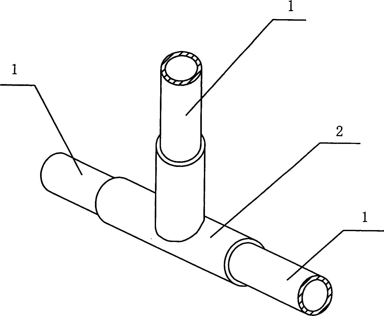
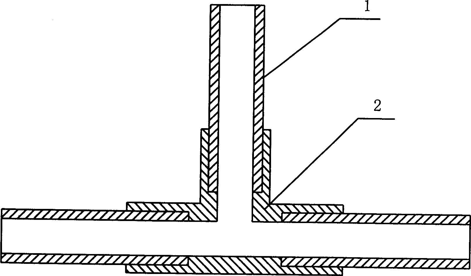
[0025] Embodiment one: see attached figure 1 and figure 2 As shown, a method for manufacturing an integrally formed pipe with a connecting portion includes the following steps:

[0026] (1) Cut and prepare 3 elastic tubes, make their length, shape, and pipe diameter meet the requirements of the integrally formed tubes to be obtained, and process their joints with methyl ethyl ketone;

[0027] (2) Insert two metal rods matching the pipe diameter into a T-shape as a forming rod, and set three elastic tubes on each branch of the forming rod respectively;

[0028] (3) Assemble the mould, so that a cavity is formed between the inner surface of the mould, the elastic tube and the forming rod;

[0029] (4) injecting thermoplastic resin into the cavity for molding;

[0030] (5) Demoulding and taking out the forming rod, the required 3-prong integral forming tube can be obtained.

[0031] The integrally formed pipe obtained in this embodiment is as attached figure 1 And attached ...

Embodiment 2

[0033] Embodiment 2: An integrally formed pipe with a connecting part, which is connected by 4 elastic pipes, one of which is a curved pipe. The manufacturing method of this embodiment is similar to that of Embodiment 1, wherein the forming The rods are composed of three metal rods in the same shape as the connecting part, and the pipes consistent with the elastic tubes can be prepared in advance.

Embodiment 3

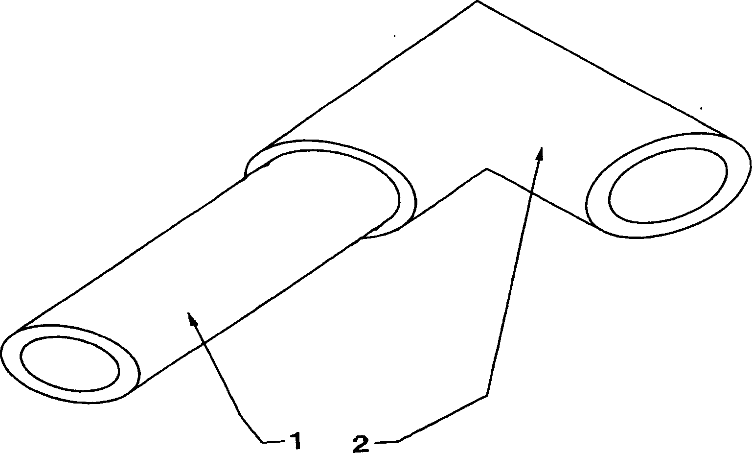
[0034] Embodiment three: see attached image 3 And attached Figure 4 As shown, an integrally formed pipe with an elbow includes an elastic pipe 1 and a connecting part 2 that acts as an elbow. The outer mold is injection molded to obtain an elbow-shaped connecting portion 2 .

[0035] This embodiment can be connected to equipment pipelines, replacing the existing connection structure of elbows and elastic tubes.


PUM


Abstract

The invention discloses a method for manufacturing an integrally formed pipe with a connecting part, which is characterized in that it comprises the following steps: preparing an elastic pipe according to the shape of the integrally formed pipe; setting the elastic pipe on a forming rod; assembling a mold to make the A cavity is formed between the inner surface of the mould, the elastic tube and the forming rod; thermoplastic resin is injected into the cavity for molding; the mold is demoulded, and the forming rod is taken out. The integrally formed pipe obtained by using the invention can replace the existing pipe joint connection mode, and because it is integrally formed, problems such as joint falling off will not occur, and the assembly workload during use is also reduced.

Description

technical field [0001] The invention relates to a method for manufacturing an integrally formed pipe, in particular to a method for manufacturing a pipe which can replace a pipe joint and integrally form a plurality of branched elastic pipes. Background technique [0002] In some machinery and equipment, especially in chemical equipment, various pipeline structures are involved. Among them, an elastic tube is often used to transport liquid or gas. When it is necessary to connect multiple elastic tubes (such as bifurcations), Or when it is necessary to connect two elastic tubes with different calibers, or even connect the elastic tube with a functional plastic device, the existing method is to use a pipe joint to sleeve the elastic tube on the pipe joint, because the elastic tube has a certain expansion ability , When the pressure inside the pipe is high, it is prone to leakage and even falls off from the pipe joint. In order to prevent the leakage o...

Claims


Application Information

Patent Timeline
Patent Type & Authority Patents(China)
IPC IPC(8): B29C65/70F16L41/08
Inventor 朱海翔
Owner 耶普(苏州)塑技有限公司
Why Eureka
Try Eureka