

Pulse pneumatic injector
A pneumatic and injector technology, which is applied in fire rescue and other fields, can solve the problems that the oil surface cannot be completely covered, the oil surface expands, and the burn is larger, and achieves the effects of small resistance, smooth injection, and short process
- Summary
- Abstract
- Description
- Claims
- Application Information
AI Technical Summary
Problems solved by technology
Method used
Image

Examples
Embodiment Construction
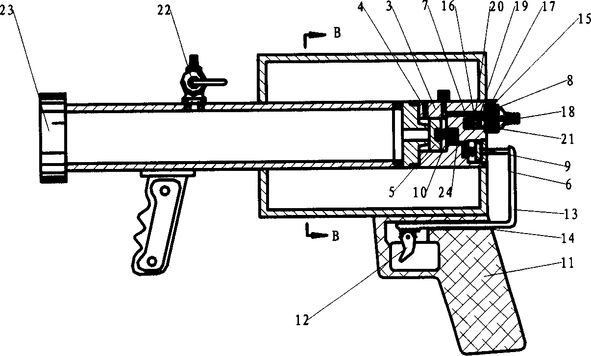
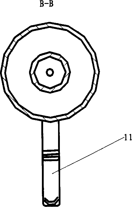
[0022] see figure 1 , a pulse air pressure injector, comprising an air storage tank; a liquid storage tank; and a multi-way combination arranged at the air inlet of the liquid storage tank for controlling the communication between the gas storage tank and the liquid storage tank valve 3. Wherein, the air storage tank is an annular cylindrical structure arranged around the liquid storage tank and the multi-way combination valve (see figure 2 ). The liquid storage cylinder is a cylindrical structure, the discharge port and the air inlet of the liquid storage cylinder are arranged at both ends of the cylindrical structure, and the multi-way combination valve 3 is arranged on the liquid storage cylinder with end of the air intake. The multi-way combined valve 3 has: a main air circuit 4 connected between the air storage tank and the liquid storage tank; a main valve 5 arranged on the main air circuit 4; the main valve 5 is controlled to open and close The control part 6; the ...
PUM
 Abstract
Description
Claims
Application Information