Conic perforator

A piercing machine and cone-shaped technology, applied in the direction of metal rolling, etc., can solve the problems of insufficient overall rigidity, difficult to compress the roll, and reduce volume, so as to achieve no stress concentration point, uniform radial force, and force reasonable effect

Inactive Publication Date: 2005-05-18
TAIYUAN TONGZE HEAVY IND
View PDF3 Cites 1 Cited by
  • Summary
  • Abstract
  • Description
  • Claims
  • Application Information

AI Technical Summary

Problems solved by technology

The disadvantage of this combined frame is that due to the welded structure, its overall rigidity is insufficient, and the wall thickness and volume of the frame must be increased to make up for its lack of strength and stability.
Secondly, the rolls of this piercing machine are set horizontally, and the upper and lower guide plate supporters are respectively installed on the upper machine cover and the lower machine base, so that the upper machine cover bears heavy pressure and high-intensity vibration during work, so , which also leads to the overall thickness of the frame to ensure the stability and reliability of the work, and another problem caused by this is that it is inconvenient to open the upper machine cover when changing the rolls, which wastes time and reduces work efficiency
Third, the existing various piercing machine frames adopt a rectangular structure in cross section. This structure has uneven radial force distribution during operation, and the stress is relatively concentrated at the intersection of the two sides.
Fourth, the overall layout of this open frame and various components centered on the frame does not break through the traditional model of the functional components of the Mann frame. Some large functional components such as guide plates and their adjustment devices are set Inside the rack, therefore, the rack itself is difficult to effectively reduce the overall weight and volume
Although the structure of this kind of piercing machine is simple, it is difficult to effectively compress the roll with only two upper and lower pressing and pressing mechanisms respectively arranged through the screw rod, especially for large-scale rolling mills.

Method used


Image

  • Conic perforator
  • Conic perforator
  • Conic perforator

Examples


Embodiment Construction

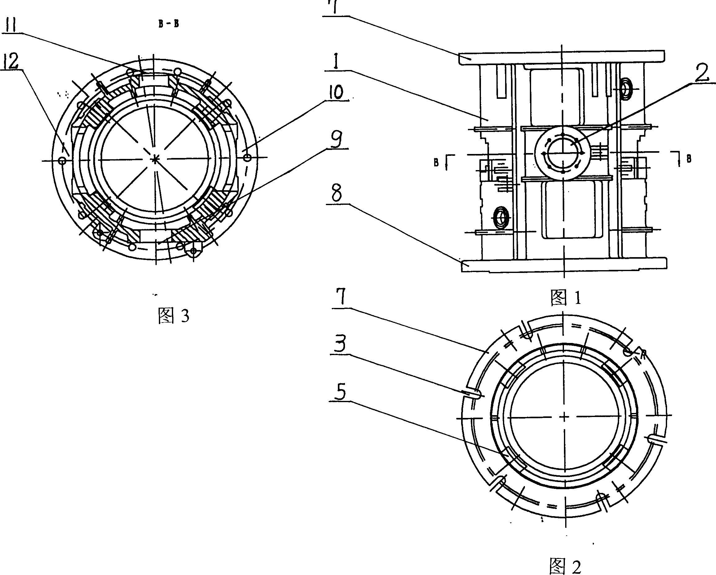
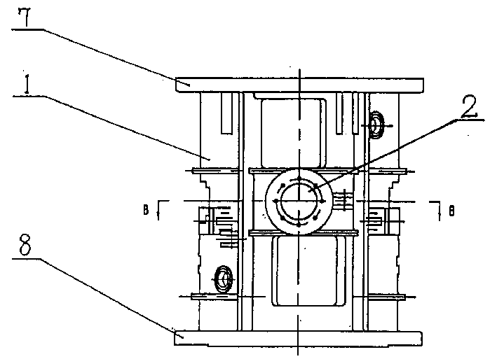
[0021] Referring to FIGS. 1-3, the frame 1 of the tapered piercer of the present invention is a cylindrical shape, which is integrally cast from low-expansion metal such as cast steel 35 or similar materials. The upper and lower outer edges 7 and 8 of the frame 1 are provided with wedge locking openings 3 for fixing with the upper cover 4 and the base 6 . There are reinforcing ribs 5 on the inner wall of the cylindrical frame, and various functional openings are arranged on different parts of the side of the cylindrical frame 1, such as the entrance 9 of the universal joint shaft that provides power for the rolls, the left guide plate opening 10, and the right guide plate opening 12 , 11 entrances of rolled blanks, 2 exits of waste pipes, etc.

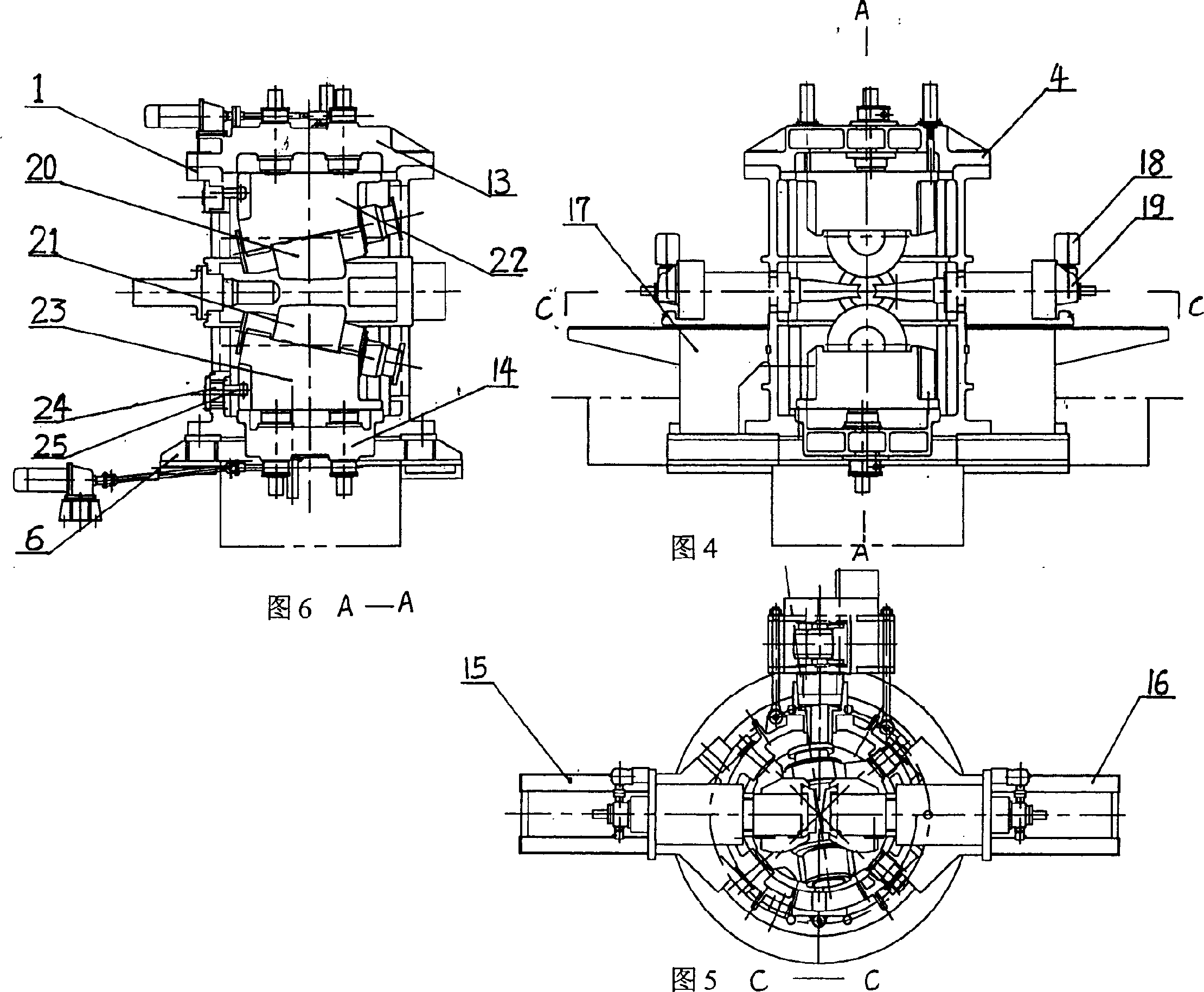
[0022] Figure 4-6 is an assembly drawing of the frame of the tapered piercing machine. There is a cover 4 on the upper part of the cylindrical frame 1 shown in the figure, and the two are locked with the wedge locking port 3 on the upp...


PUM


Abstract

A conical piercing machine, comprising a frame, with an upper cover and a base on the upper part and the bottom of the frame respectively; two drums placed in the frame and two rollers respectively installed on the drums; The guide plate and its adjustment device, the frame is a cylindrical body with a circular cross-section integrally cast from low-expansion metal. The guide plate adjustment device of the tapered piercer is placed outside the frame as a whole, and is locked on the frame with a wedge. The distance of the guide plate relative to the center line is adjusted by means of a motor operated horizontally arranged screw jack. Because the tapered piercing machine of the present invention adopts the integral casting frame of the cylindrical structure, the casting material of the frame can be greatly saved, and the overall rigidity of the frame is enhanced, and the force during the perforation operation is more reasonable, especially the radial force is uniform, There are no stress concentration points.

Description

technical field [0001] The invention relates to a pressure processing equipment in the field of metallurgical industry technology, in particular to a two-roller cross-rolling hot-rolling device used in the hot-rolled seamless steel pipe unit to complete the first main rolling deformation process to perforate the heated billet into a blank tube. Tube piercer. But the present invention is not limited to the above-mentioned two-roller cross-rolling hot-rolled pipe piercing machine, and can also be used in other piercing machines. Background technique [0002] The existing two-roller cross-rolling piercers for hot-rolled seamless steel pipe units are roughly divided into two categories. The first category is the traditional Mans piercer invented in the early days. The shape of the rolls is a barrel structure. Requirements, a barrel-type frame with a rectangular cross-section is adopted, which is usually cast as a whole and weighs more than 50 tons. The disadvantages of this fra...

Claims


Application Information

Patent Timeline
Patent Type & Authority Patents(China)
IPC IPC(8): B21B19/04
Inventor 郭继保杨泽姚建社
Owner TAIYUAN TONGZE HEAVY IND
Why Eureka
Try Eureka