Silencer of rotary compressor

A technology of rotary compressor and muffler, which is applied in machine/engine, rotary piston/oscillating piston pump components, mechanical equipment, etc., can solve the problem of the overall performance degradation of the compressor, and it is difficult to effectively reduce noise in specific bands, etc. question

Inactive Publication Date: 2005-06-08
LG ELECTRONICS (TIANJIN) APPLIANCES CO LTD
View PDF0 Cites 0 Cited by
  • Summary
  • Abstract
  • Description
  • Claims
  • Application Information

AI Technical Summary

Problems solved by technology

Although this kind of muffler can reduce noise in a wide frequency range, it is difficult to effectively reduce noise in a specific band
In addition, this muffler will also increase the input pressure of the compressor, thereby reducing the overall performance of the compressor

Method used


Image

  • Silencer of rotary compressor
  • Silencer of rotary compressor
  • Silencer of rotary compressor

Examples


Embodiment Construction

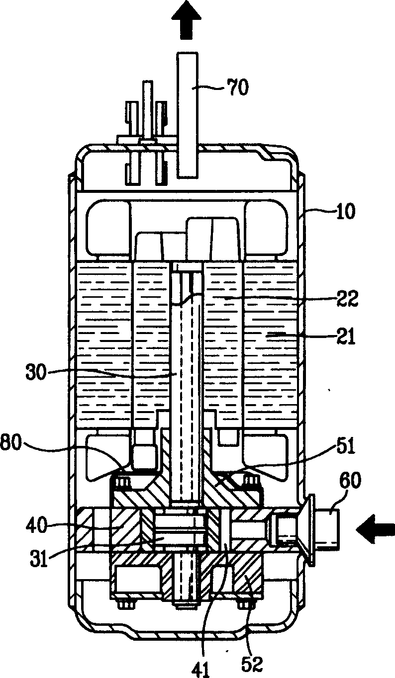
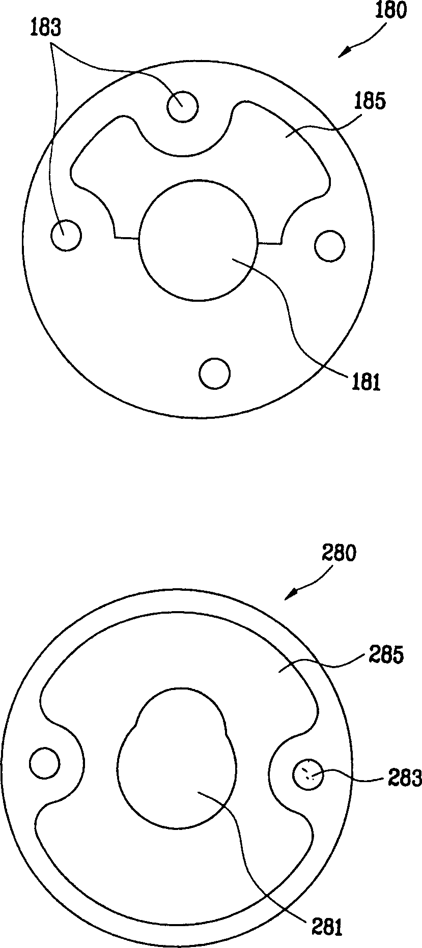
[0017] refer to figure 1 , image 3 , Figure 4 As shown, the rotary compressor muffler of the present invention includes an inner muffler 180 installed on the upper part of the main bearing 51 and an outer muffler 280 installed on the upper end of the inner muffler 180, thus having two functions of reducing noise.

[0018] The inner muffler 180 is formed by the crankshaft insertion space 181 through which the central crankshaft 30 is inserted, and an assembly groove 183 for fixing the inner muffler 180 on the main bearing 51 is formed at its edge position. In this embodiment, the assembly grooves 183 are respectively They are provided at four places in the front, back, left, and right of the edge portion of the internal muffler 180 . The middle part of one side of the internal muffler 180 is the compression chamber 41 refrigerant gas discharge space 185 formed on the top of the main bearing 51 and the outer surface of the crankshaft 30, and this discharge space 185 is open ...


PUM


Abstract

The rotary compressor muffler consists of an inner muffler installed on the main bearing of the compressor crankshaft and an outer muffler installed above the inner muffler. The middle part of one side of the inner muffler forms a discharge space for refrigerant gas in the compression chamber. An inner muffler refrigerant gas discharge space is formed in the muffler. The present invention not only has the function of a general muffler to reduce noise in a wide frequency range, but also has the function of a resonator to reduce specific frequency noise, and prevents the increase of the input pressure of the compressor, thereby avoiding the decline of the overall performance of the compressor.

Description

1. Technical field: [0001] The invention relates to a rotary compressor muffler, in particular to a muffler capable of further reducing the noise of refrigerant gas discharged from a compression chamber. 2. Background technology: [0002] Generally speaking, the compressor sucks the refrigerant gas evaporated by the evaporator and compresses it to the saturation pressure, and then discharges it. The rotary compressor is a compressor that can continuously suck and discharge the refrigerant gas. [0003] Depend on figure 1 It can be seen that the stator 21 and the rotor 22 of a general rotary compressor are installed in the airtight container 10, the center of the rotor 22 is combined with the crankshaft 30, and the lower end of the crankshaft 30 is integrated with the eccentric member 31, so that the inside of the gas cylinder 40 The formed compression chamber 41 is rotatable. In addition, in order to make the crankshaft 30 run smoothly, a main bearing 51 and an auxiliary b...

Claims


Application Information

Patent Timeline
Patent Type & Authority Patents(China)
IPC IPC(8): F04C29/06
Inventor 金永宗河宗勋
Owner LG ELECTRONICS (TIANJIN) APPLIANCES CO LTD
Why Eureka
Try Eureka