Optical coupling

An optical coupling and optical axis technology, applied in the field of optical coupling systems, can solve the problems of difficult to establish spacing and alignment, and achieve the effect of uniform bonding and reliable bonding

Inactive Publication Date: 2005-06-29
LUMENTUM OPERATIONS LLC
View PDF0 Cites 1 Cited by
  • Summary
  • Abstract
  • Description
  • Claims
  • Application Information

AI Technical Summary

Problems solved by technology

However, this method makes it difficult to establish a precise spacing and alignment

Method used


Image

  • Optical coupling
  • Optical coupling
  • Optical coupling

Examples


Embodiment Construction

[0035]An optical coupling is provided, ideally using two ferrules with complementary end faces to provide optical coupling between an optical fiber and a lens spaced from each other. The coupling described here does not require adhesives in the optical path and provides considerable flexibility in the optical alignment of the fiber to the lens while providing a reliable and stable joint.

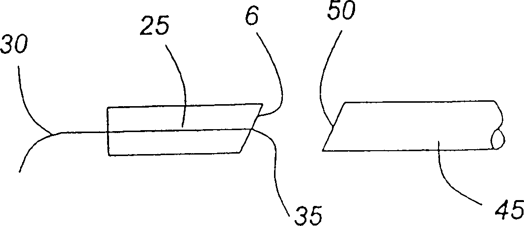
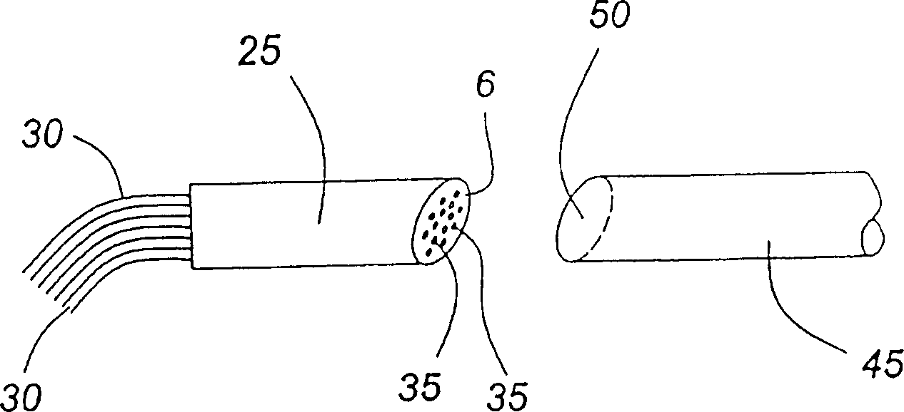
[0036] Referring to FIG. 1 , there is shown a cross-sectional side view of known elements to be optically coupled, namely an optical fiber 30 and a lens 45 . The lens 45 is used for guiding a beam of light into the optical fiber and / or for receiving a beam of light from the optical fiber 30 . Optical fiber 30 is contained within a fiber optic tube / ferrule 25 which supports and secures optical fiber 30 thereto. The fiber tube 25 has an end 6 and the optical fiber 30 has an end 35 . The ends are polished flush. Ends 35 and 50 are polished to the same complementary non-right angle. For simp...


PUM


Abstract

The present invention relates to an optical coupling between a first lens end and a second lens end, providing a reliable joint with a predetermined spacing and angular orientation. The optical coupling allows movement of the first lens end relative to the second lens in at least two alignment directions. Advantageously, the invention allows the first lens end to move relative to the second lens end in a direction perpendicular to the optical axis of the lens before the optical coupling is fixed. The first and second lenses are secured within separate sleeves and the sleeves are secured together. The first end and the second lens end are optically aligned prior to being fixed in place with each other.

Description

technical field [0001] The present invention relates to an optical coupling system, in particular to a connection system providing a reliable joint between optical elements. In particular, the invention provides optical coupling between an optical fiber and a lens or between two lenses. Background technique [0002] The most common optical connection employed in the manufacture of optical devices is between an optical fiber and a lens such as a graded index (GRIN) lens. There are generally two ways to obtain a connection. A common coupling system consists of a ferrule where one fiber end within the support housing / ferrule is connected to the lens by connecting the ferrule and the sides of the lens to the lumen of the ferrule. For example, manufacturing tolerances in the size and location of the lens diameter, ferrule diameter, or ferrule lumen can introduce variances that make precise alignment difficult to achieve with this type of connection. The ferrule must have suffi...

Claims


Application Information

Patent Timeline
Patent Type & Authority Patents(China)
IPC IPC(8): G02B6/26G02B6/32G02B6/34G02B6/36
CPCG02B6/262G02B6/266G02B6/2746G02B6/2937G02B6/29389G02B6/29395G02B6/32G02B6/327
Inventor 程颐浩
Owner LUMENTUM OPERATIONS LLC
Why Eureka
Try Eureka