
Spinal fusion implant

A technology for implants and spine, applied in the field of repairing implants, can solve the problems of difficulty in achieving fusion and insufficient support for heavy load

Inactive Publication Date: 2005-07-06
DEPUY ACROMED INC
View PDF2 Cites 0 Cited by
  • Summary
  • Abstract
  • Description
  • Claims
  • Application Information

AI Technical Summary

Problems solved by technology

Most devices are difficult to achieve fusion at least without the help of some auxiliary fixation devices such as rods, plates, etc.
Also, some devices are not structurally adequate to support the heavy loads most frequently placed on the fused vertebrae, primarily in the lower lumbar spine

Method used


Image

  • Spinal fusion implant
  • Spinal fusion implant
  • Spinal fusion implant

Examples


Embodiment Construction

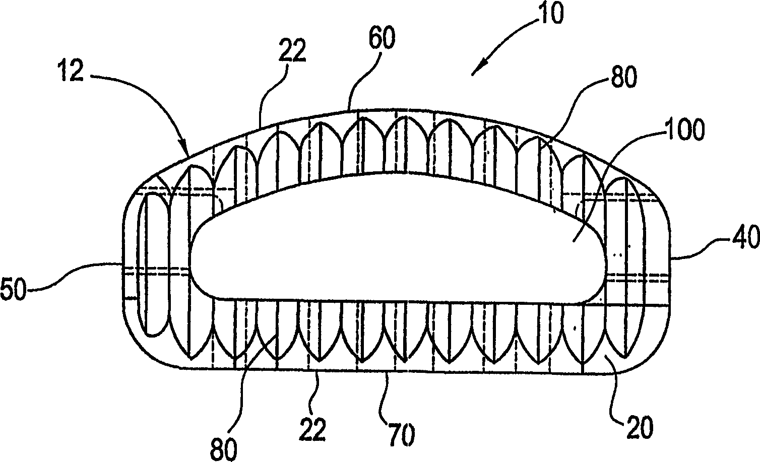
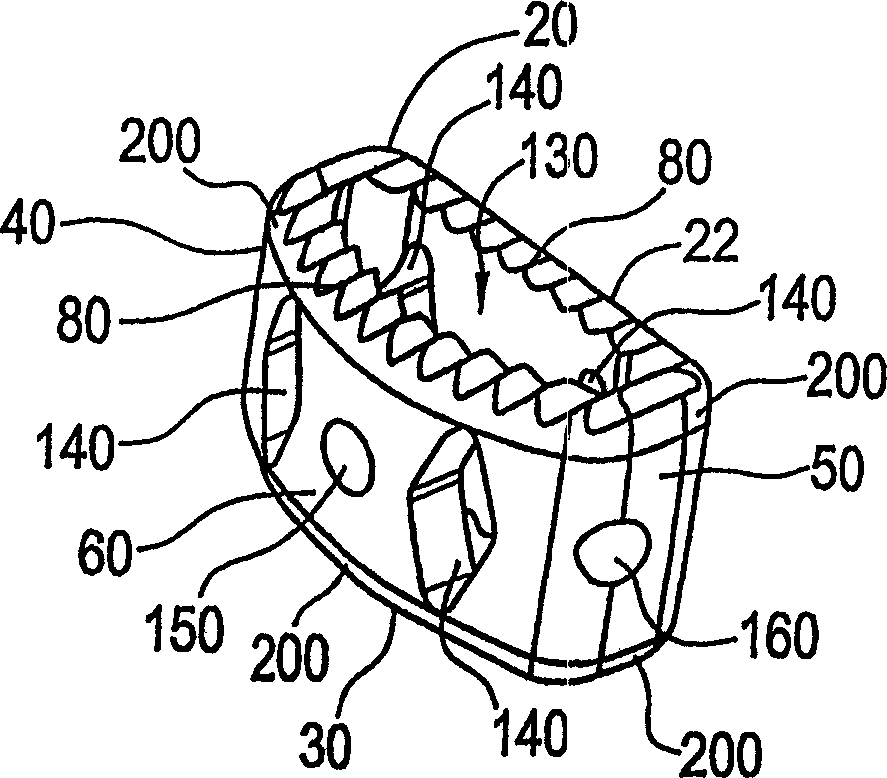
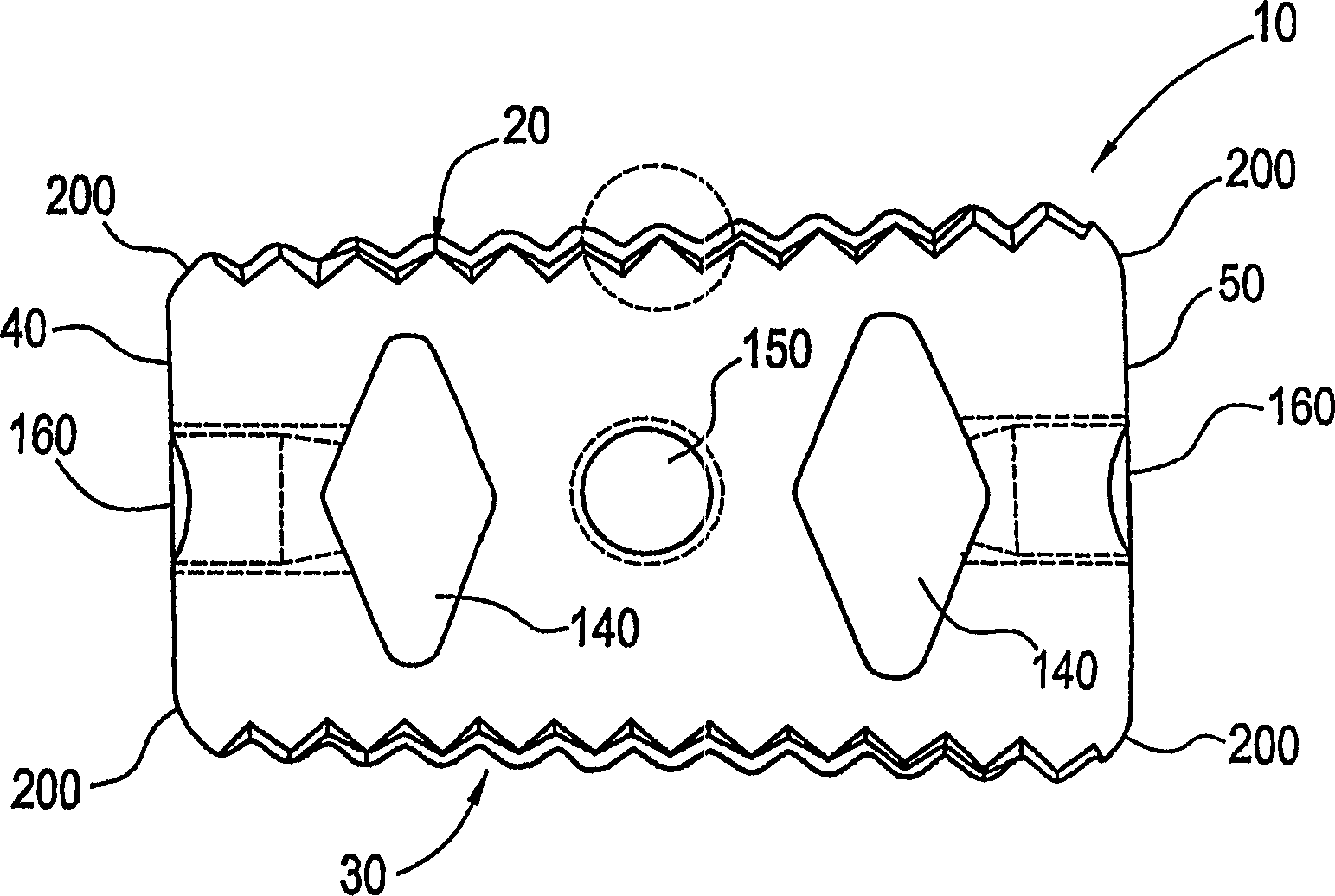
[0051] Referring to the accompanying drawings, the accompanying drawings are only used to illustrate the preferred embodiment of the present invention and are not intended to limit the embodiment, Figure 1-Figure 3 is a prosthetic device or prosthetic graft 10 designed to be inserted between two vertebrae in the intervertebral disc space and in the spine. A frame-like structure 12 as shown in prosthetic graft 10 has a top wall 20 , a bottom wall 30 , a front end wall 40 , a rear end wall 50 , a first side wall 60 and a rear side wall 70 . as best shown in figure 1 and figure 2 Here, the top wall 20 is composed of a plurality of protrusion structures 80 arranged along the longitudinal length of the prosthetic graft 10 . Such as image 3 As shown, the protruding structure 80 is included on the bottom wall 30 . The raised structures can be cut into the top and bottom walls and / or formed by molding. The protruding structure is designed as a rigid contact with the lower surf...


PUM


Abstract

An improved revision graft (10) forms a rigid structure (12) between adjacent vertebrae in the spine. The repair graft (10) includes a framework (12), which has a top wall (20), a bottom wall (30), a front end wall (40), a rear end wall (50), a first side wall (60) and a second side wall (70). The first side wall (60) has an arcuate surface. The top wall (20) and bottom wall (30) contain one or more protrusions (80) to engage the surface of the adjacent vertebrae. The top wall (20) and bottom wall (30) also contain a through hole (100) for receiving a filling substance (300), such as medicine, human tissue and the like. The top wall (20) and the bottom wall (30) are inclined in two directions simultaneously.

Description

technical field [0001] The present invention relates to a prosthetic graft joining together two or more vertebrae, in particular a prosthetic graft embedded in the spine of the body. Background technique [0002] This invention is claimed from U.S. Patent Application No. 09 / 494,645, filed January 31, 2000, which claims U.S. Patent Application No. 60 / 121,705, filed February 1999 On the 25th, priority was granted to a US patent entitled "Spine Fusion Implant." [0003] This application incorporates by reference US Patent Application No. 60 / 121,705, filed February 25, 1999, entitled "Spinal Fusion Graft". [0004] The human spine is composed of 33 vertebrae and their connecting structures. As we all know, the vertebrae near the head are the presacral vertebrae, and they can move independently. The main bodies of the vertebrae are connected by ligaments and fibrocartilaginous discs known as intervertebral discs at the front and back. These discs are located between opposing ...

Claims


Application Information

Patent Timeline
Patent Type & Authority Patents(China)
IPC IPC(8): A61F2/44A61F2/00A61F2/28A61F2/30A61F2/46
CPCA61F2/30965A61F2/442A61F2/4455A61F2/4611A61F2002/2835A61F2002/30151A61F2002/30187A61F2002/30593A61F2002/30774A61F2002/30787A61F2002/30904A61F2002/448A61F2230/0017A61F2230/0034A61F2310/00017A61F2310/00023A61F2310/00029Y10S606/908Y10S606/909Y10S606/91Y10S606/911Y10S606/912
Inventor 罗伯特·S·比斯科普
Owner DEPUY ACROMED INC
Learn More