Mobile communication mode and radio receiver

A radio receiver and frame receiving technology, applied in wireless communication, radio/induction link selection and arrangement, electrical components, etc., can solve the problem of large equipment investment, and achieve the effect of expanding service area and high-quality transmission service

Inactive Publication Date: 2005-08-03
KOKUSA ELECTRIC CO LTD
View PDF4 Cites 0 Cited by
  • Summary
  • Abstract
  • Description
  • Claims
  • Application Information

AI Technical Summary

Problems solved by technology

In this way, in such a less densely populated area, the amount of equipment investment for each user becomes larger

Method used


Image

  • Mobile communication mode and radio receiver
  • Mobile communication mode and radio receiver
  • Mobile communication mode and radio receiver

Examples


Embodiment Construction

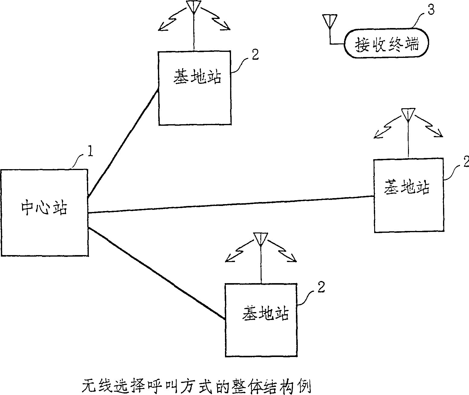
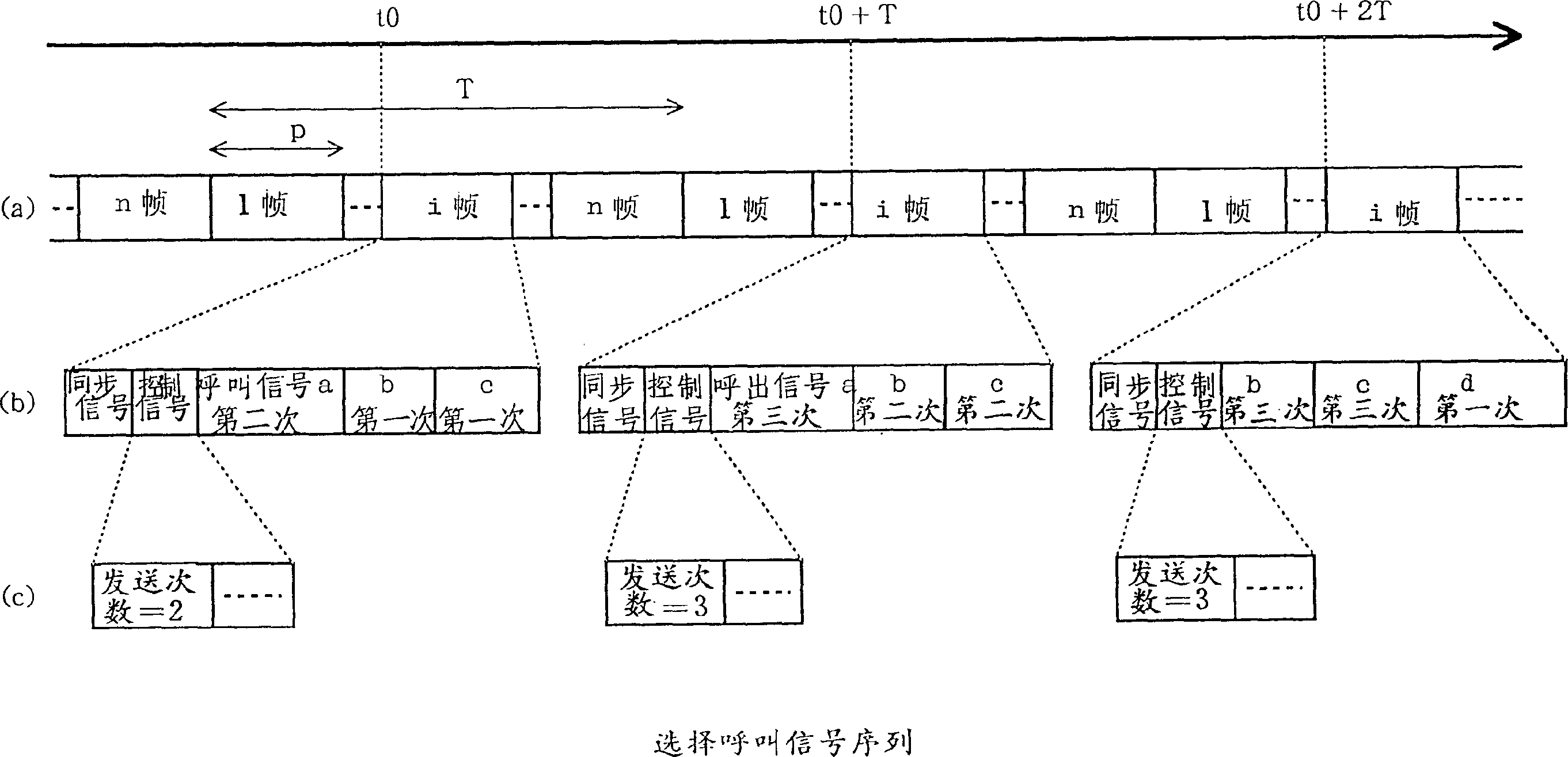
[0032] figure 1 A block diagram showing the implementation of the wireless selective calling method of the present invention, figure 2 An example of a selective call signal sequence transmitted by a base station is shown. In this wireless selective calling method, a plurality of base stations are arranged as a transmitting device for transmitting a call signal for selectively calling a receiving terminal to a multiple wireless zone, and a center station is provided with 2 base stations for variably setting The device that sends the number of times the call signal is sent.

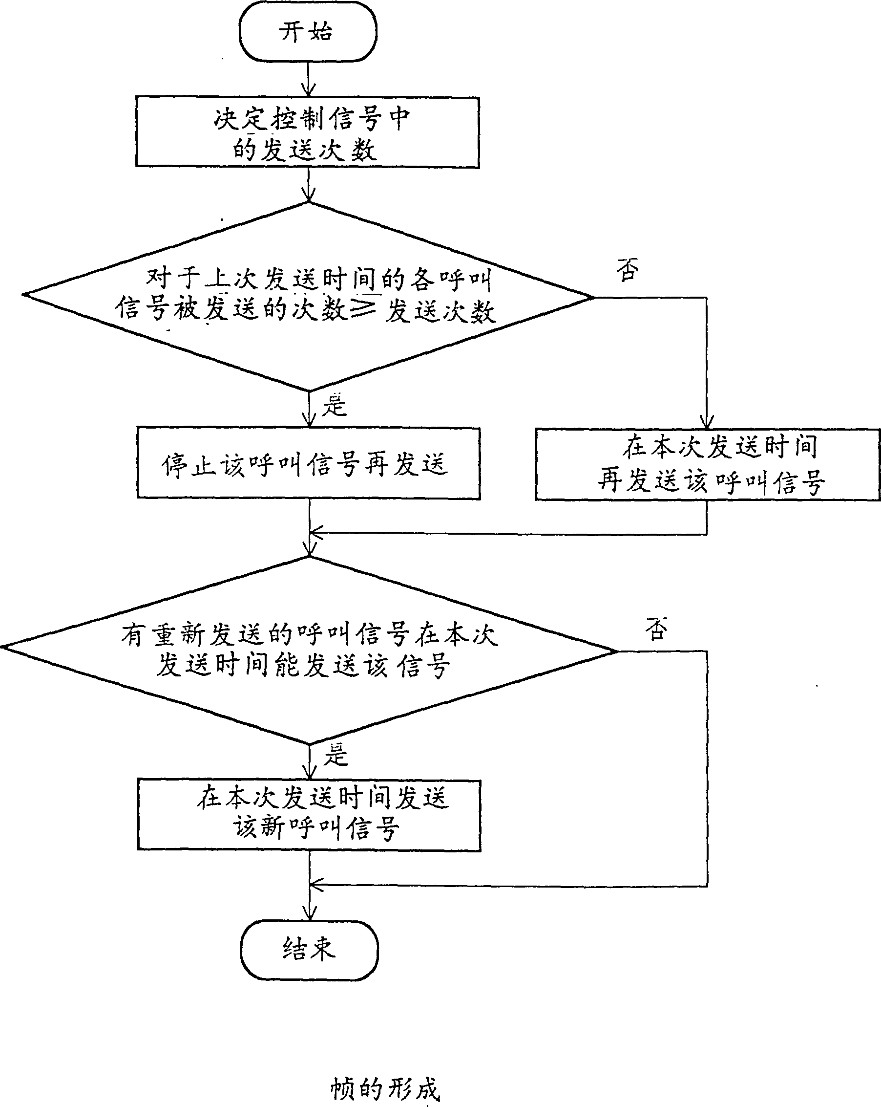
[0033]The center station 1 forms a frame composed of synchronization signal, control signal and call signal sequence according to the call requirement from the fixed network and transmits it to the base station 2 through the trunk line. The base station 2 transmits this frame to the wireless section. In order to designate the transmission parameters and mode and switch the receiving terminal, informatio...


PUM


Abstract

A system which transmits a calling signal to radio sections to selectively call a radio receiver. The number of times of transmission of the calling signal from a base station is variable, so that the facility of the base station can be built at a relatively low cost even when the number of subscribers per service area is small.

Description

[0001] The present invention is a divisional application of Chinese patent application 95190059.5. technical field [0002] The present invention is used for calls to radio receivers. In particular, it relates to a mobile communication method and a receiver for repeatedly sending a signal for selectively calling a receiver. Background technique [0003] The technology of selectively calling a mobile station is a well-known technology in mobile communication. For the sake of simplicity, an example will be given below to illustrate the wireless selective calling method using a special mobile station for reception. [0004] figure 1 An example of the overall structure of the wireless selective calling system is shown. This system is configured with a central office 1 and a plurality of base stations 2, and a call signal sequence is transmitted from the central office 1 through a trunk line to a base station 2, which transmits the call signal sequence to a radio transmission s...

Claims


Application Information

Patent Timeline
Patent Type & Authority Patents(China)
IPC IPC(8): H04W88/18
CPCH04W88/187H04W88/18
Inventor 伊藤正悟山尾泰大久保信三
Owner KOKUSA ELECTRIC CO LTD
Why Eureka
Try Eureka