Solar heat harnessing system

A solar heat transfer system technology, applied in the field of solar heat utilization systems, can solve the problems of heat collector 70 design, manufacture, maintenance troubles, increase costs, etc., to achieve easy manufacture and maintenance, reduce strength and machine capacity, structure simple effect

Inactive Publication Date: 2005-08-10
阿贺田隆启
View PDF0 Cites 0 Cited by
  • Summary
  • Abstract
  • Description
  • Claims
  • Application Information

AI Technical Summary

Problems solved by technology

In addition, it is necessary to maintain the approximate vacuum of the gap 72c and the gap 73, and the design, manufacture, and maintenance of the heat collector 70 are troublesome.
As a result, the ease of further cost increases becomes a problem

Method used


Image

  • Solar heat harnessing system
  • Solar heat harnessing system
  • Solar heat harnessing system

Examples


Embodiment Construction

[0053] Hereinafter, embodiments of the solar heat utilization system according to the present invention will be described with reference to the drawings. Also, the same symbols are used for components that have the same function as the previous system.

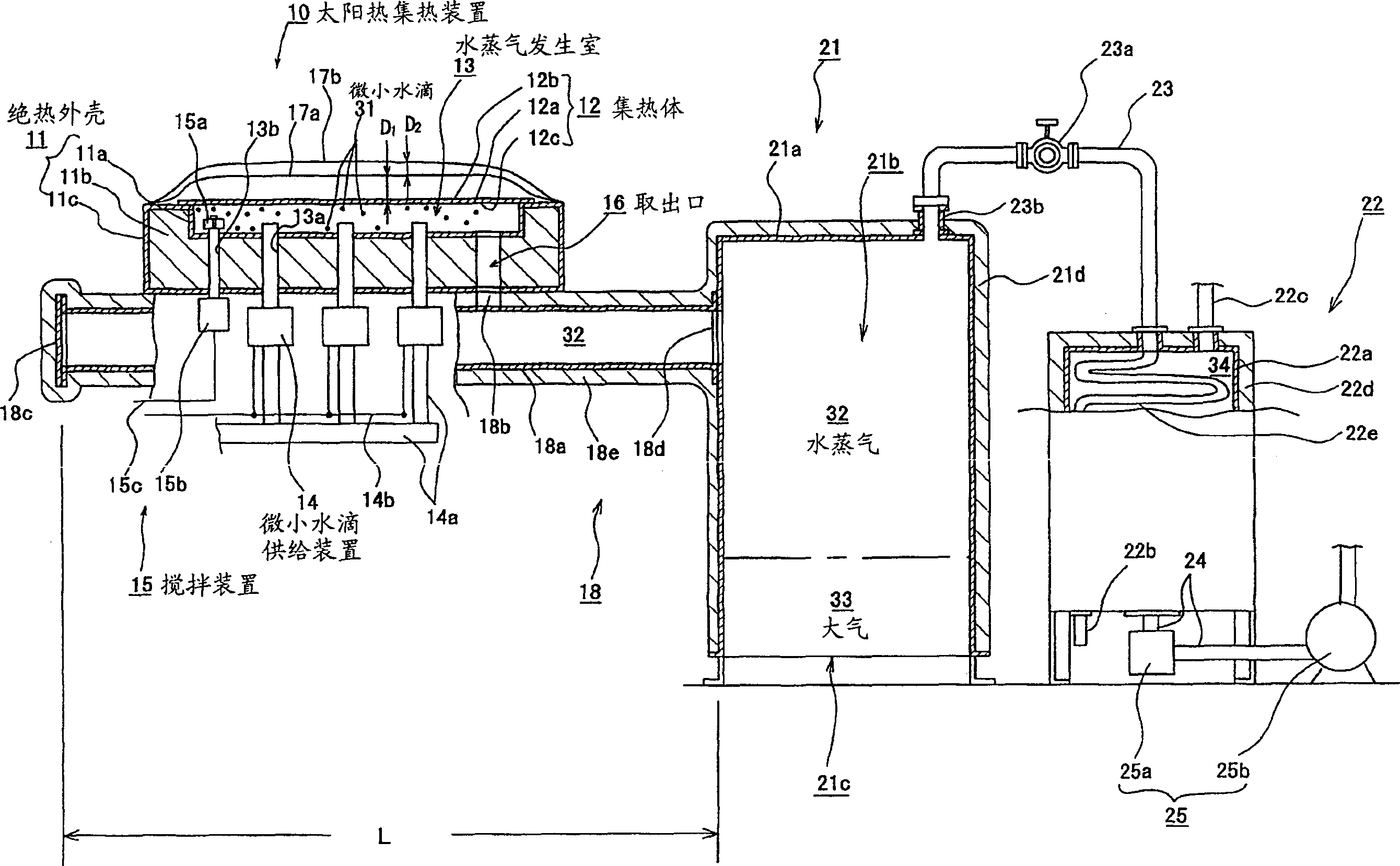
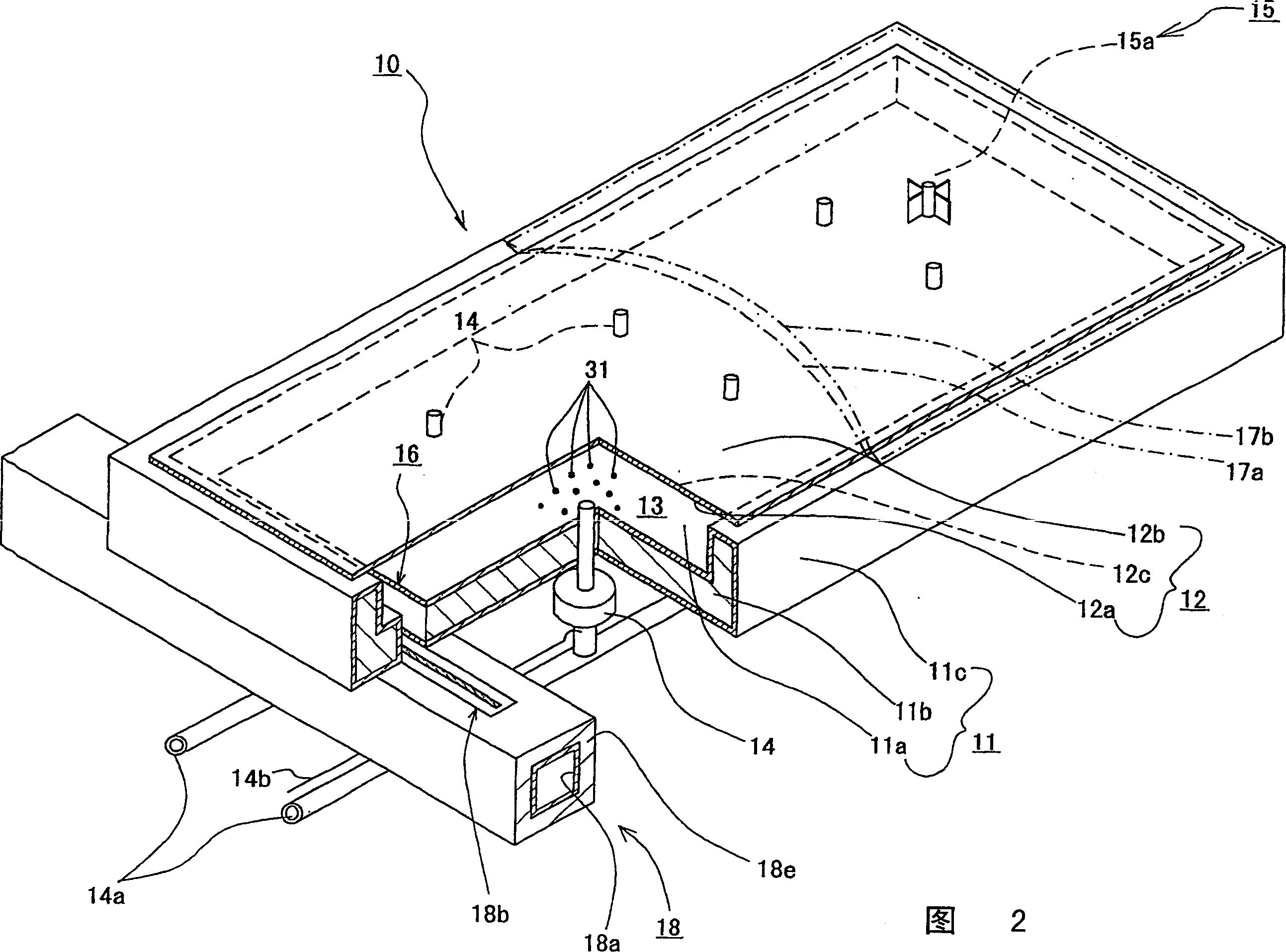
[0054] figure 1 It is a sectional view schematically showing the solar heat utilization system according to the embodiment (1), and Fig. 2 is a partial sectional oblique view showing in detail the vicinity of the heat collector of the solar heat utilization system according to the embodiment (1). The frame 11a is made of a thin plate such as stainless steel or plastic material, and is roughly box-shaped. A heat insulating member 11b is disposed on the outer periphery of the frame 11a, and the heat insulating member 11b is protected by a protective member 11c. The heat insulating case 11 is comprised by these frame 11a, heat insulating member 11b, and protective member 11c.

[0055] A metal plate 12a is closely attached to ...


PUM


Abstract

The present invention was achieved in order to provide a solar thermal system, wherein using a small amount of water as a medium, solar thermal energy can be largely and efficiently collected as latent heat of saturated steam or superheated steam with 1 atmospheric pressure, and the generated saturated or superheated steam is automatically transported to be stored with ease and certainty, so that the light weight and downsizing of the apparatus are achieved, and that the apparatus can be easily designed, produced and maintained, resulting in a substantial reduction in cost, which comprises a steam generating chamber to evaporate droplets by solar heat therein, being formed between an absorbing body and a heat insulation case, and a droplet supply means to supply droplets into the steam generating chamber, wherein steam generated in the steam generating chamber is used as a heating medium.

Description

technical field [0001] The invention relates to a solar heat utilization system. The specific solar heat utilization system involved is a system that utilizes the state of saturated water vapor or superheated water vapor close to atmospheric pressure to utilize solar heat. Background technique [0002] Figure 5 It is a partial cross-sectional oblique view schematically showing the main parts of the conventional solar heat utilization system, and 51 in the figure is a heat collecting plate. The heat collecting plate 51 is made of stainless steel plate, aluminum plate, etc., and its plane is roughly rectangular. The upper surface 51a of the heat collecting plate 51 is black-painted (not shown), and solar heat can be easily absorbed by this black-painted treatment. A plurality of roughly tubular heat collecting tubes 52 made of copper, stainless steel and other metals are arranged in parallel at predetermined positions of the heat collecting plate, and ...

Claims


Application Information

Patent Timeline
IPC IPC(8): F22B1/00F22B27/16F24S10/95F24S90/00
CPCF24J2/32F22B1/006F22B27/16Y02E10/44F24J2/42F24S10/95F24S90/00Y02E10/40
Inventor 阿贺田隆启
Owner 阿贺田隆启
Why Eureka
Try Eureka