Braking device

A brake system, brake lever technology, applied in the direction of brake types, drum brakes, brake actuators, etc.

Inactive Publication Date: 2005-08-17
斯文·马尔姆斯特伦
View PDF0 Cites 0 Cited by
  • Summary
  • Abstract
  • Description
  • Claims
  • Application Information

AI Technical Summary

Problems solved by technology

The straps have the same drawback and must be adjusted after the handle has been moved; the metal rod sticks out of the tube and traps items outside

Method used


Image

  • Braking device
  • Braking device
  • Braking device

Examples


Embodiment Construction

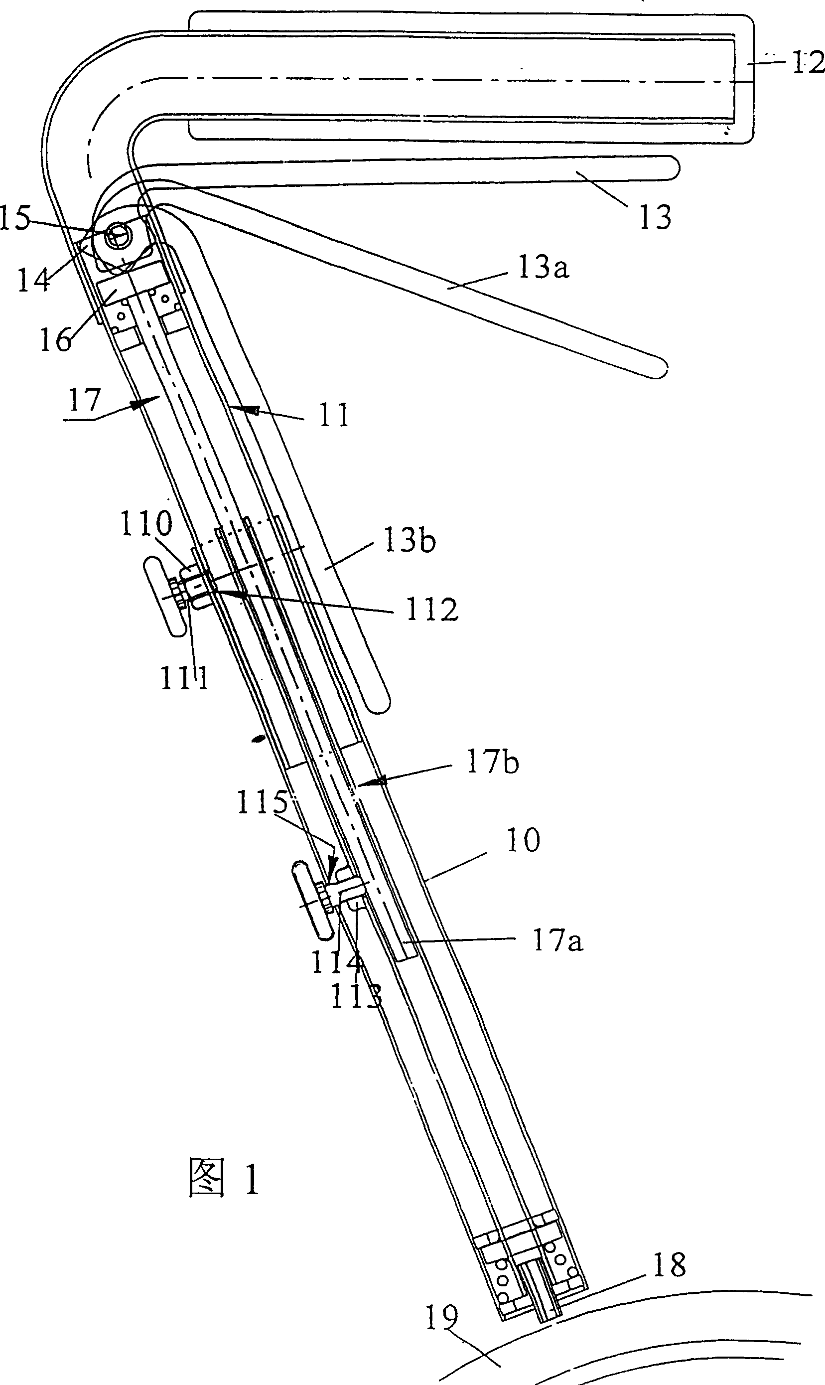
[0008] Referring to Figure 1, an outer frame tube 10 and an inner frame tube 11 together form a support for a handle 12 and a brake lever which is pivotable about an axis 15, the handle having three different positions as shown : a braking position 13, a release position 13a and a locking position 13b. The brake lever has a pressure surface 14 for contacting a spring biased plate 16 which acts on the upper end of a rod 17a which is an integral part of a retractable brake rod 17; The part is a tube 17b into which the rod 17a can be inserted, and a braking device 18 is screwed into the lower end of the tube, and the screw lock is pressed against a walking frame wheel 19 when braking. (only a part is shown in the figure). Since the wheeled walker is to be adapted to both tall and short people, the handles must be able to be raised and lowered and then fixed when adjusted. For this reason, an internally threaded hole 110 is provided on the top of the outer frame pipe 10, such as...


PUM


Abstract

A brake system for a wheeled walker frame having two walker frame legs with two telescopically adjustable frame tubes, of which one frame tube supports in its upper region a handle and a brake lever and the other is provided in its lower region with a brake device for braking a wheel. A telescopically adjustable brake rod is disposed within the frame tubes, between the brake lever and the brake device, and includes two parallel rods of which one is interconnected with the brake lever and the other is interconnected with the brake device. An axial longitudinal adjustment of the frame tubes to the desired vertical position synchronously causes a corresponding alteration of the length of the brake rod. At least one device is provided for locking the frame tubes and the parallel rods.

Description

technical field [0001] The invention relates to a braking system. Background technique [0002] This type of wheeled walker is usually made of metal and is stable, durable and lightweight. According to the laws of most European countries, certain requirements must be met in order to use a wheeled walker in public health care. It should have as hygienic an appearance as possible, i.e. a clean, smooth surface with few pits and protrusions where dust can hide. Furthermore, each handle should have a detent, and the handles can also be adjusted vertically as easily as possible, during which detents should preferably be adjusted synergistically or very easily. A quick glance at the prior art reveals that there are roughly three methods of transferring braking force from the handle to the brake: a) a hose; b) a strap; c) a metal rod, all or part of which Outside of metal tubes, this is the shortcoming of the braking systems of the prior art. The hose loops, and these loops can ...

Claims


Application Information

Patent Timeline
Patent Type & Authority Patents(China)
IPC IPC(8): F16D49/00A61H3/04B62B5/04F16D65/28
CPCA61G5/101A61H2003/046A61H3/04A61G5/1018B62B5/0485A61G5/1035A61G5/1005
Inventor 斯文·马尔姆斯特伦
Owner 斯文·马尔姆斯特伦
Why Eureka
Try Eureka