Method for converting electrical energy into thermal energy and electrical heating device using same

A technology of electric energy conversion and thermal energy, applied in coil devices, induction heating, induction heating control, etc., can solve problems such as increasing efficiency

Pending Publication Date: 2021-06-25
利涅维奇艾迪韦德伊凡诺维奇 +1
View PDF2 Cites 0 Cited by
  • Summary
  • Abstract
  • Description
  • Claims
  • Application Information

AI Technical Summary

Problems solved by technology

[0007] The present invention solves the technical problem of increasing the efficiency of converting electrical energy into heat for use in various processes

Method used


Image

  • Method for converting electrical energy into thermal energy and electrical heating device using same
  • Method for converting electrical energy into thermal energy and electrical heating device using same
  • Method for converting electrical energy into thermal energy and electrical heating device using same

Examples


Embodiment Construction

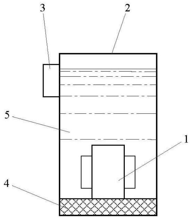
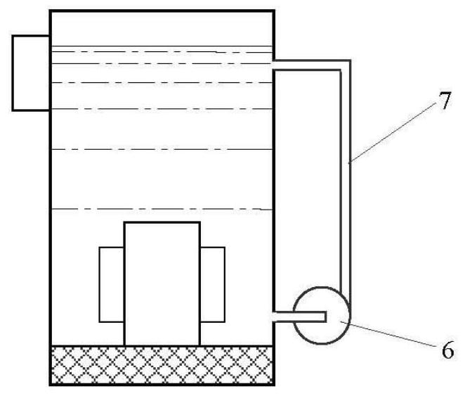
[0027] Throttle valve 1 is used with unpressurized windings and cores to improve the ability to impregnate them with liquid heat carrier 5 . After dipping, the leakage current through the insulator is reduced, the electrical breakdown resistance is increased, and the heat transfer from the heating element to the heat carrier 5 is maximized. Capacitor 10 may be located outside or inside tank 2 . In the second case, the heat from the capacitor is also transferred to the heat carrier 5 . As the heat carrier 5, any liquid substance such as transformer oil, glycerin, paraffin (liquid), etc. that does not damage the insulation of parts and materials located inside the storage tank 2 can be used. The spacer 4 is intended to dampen the effects of vibrations produced by the core of the throttle valve 1 .

[0028] When the switch 13 is closed, the electrical part of the heater 15 immediately goes into ferroresonant mode. It provides all circuit details and correct selection of AC pow...


PUM


Abstract

The invention relates to an electric heating device, which can be used to mainly heat liquids and gaseous substances, and particularly can be applied to the creation of effective devices and heating systems for residence and industrial sites. According to the invention, a throttle valve is used to heat a heat carrier connected in parallel or in series with a capacitor in an electrical circuit to an AC power source while the value is used to select the electrical parameter of the electrical circuit to provide a ferromagnetic resonance mode.

Description

technical field [0001] The present invention relates to an electric heating device which can be used primarily for heating liquid and gaseous substances. The invention can be applied to create appliances and heating systems for residential and industrial premises. Background technique [0002] Patent RU2075838 describes a device for heating a fluid comprising a tube made of diamagnetic material covering its inductor, a core mounted inside the tube such that between the surface of the core and the inner surface of the tube There is an annular gap between them; the pipeline for supplying liquid and the pipeline for collecting liquid, characterized in that the core is made in the form of a tube, its end hole is closed by a cover, and the wall thickness is set to 3-5mm, so that the antimagnetic tube The size of the annular gap between the inner surface of the loss and the outer surface of the core is 1.5-5 mm, and the nozzle for entering and exiting the fluid communicates with ...

Claims


Application Information

Patent Timeline
IPC IPC(8): H05B6/36H05B6/06
CPCH05B6/36H05B6/06
Inventor 利涅维奇·艾迪韦德·伊凡诺维奇季莫费耶夫·安德雷·维克特瑞维奇
Owner 利涅维奇艾迪韦德伊凡诺维奇
Why Eureka
Try Eureka