
Fixing device

A technology of fixing device and clamping device, which is applied in the direction of bearing, printing, rotary printing machine, etc., can solve the problems of inability to transfer ink, damage of elastic roller extrusion work, etc., and achieve the effect of compact structure

Inactive Publication Date: 2005-09-07
KOENIG & BAUER AG
View PDF3 Cites 0 Cited by
  • Summary
  • Abstract
  • Description
  • Claims
  • Application Information

AI Technical Summary

Problems solved by technology

For example, if the contact belt in the printing unit is too narrow, sufficient ink cannot be transferred, whereas if the contact belt is too wide, the elastic roller will be damaged by the pressing work generated in it.

Method used

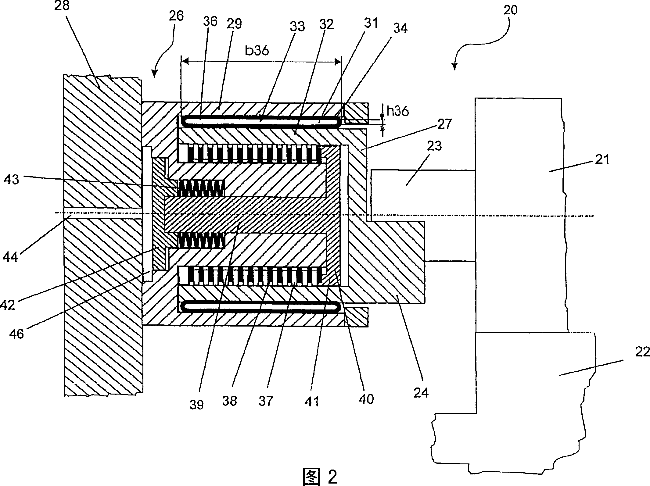
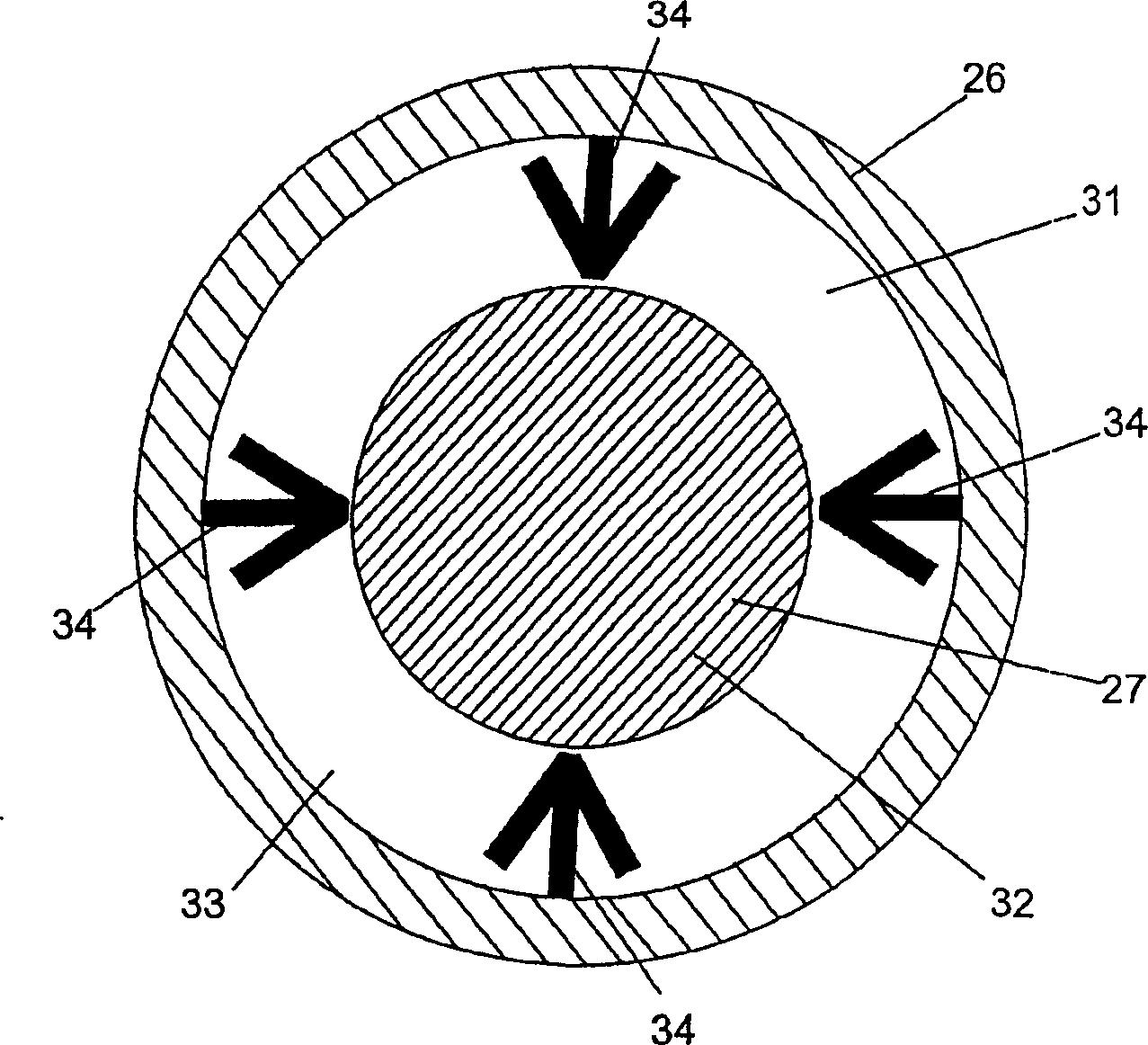

Image

  • Fixing device
  • Fixing device
  • Fixing device

Examples


Embodiment Construction

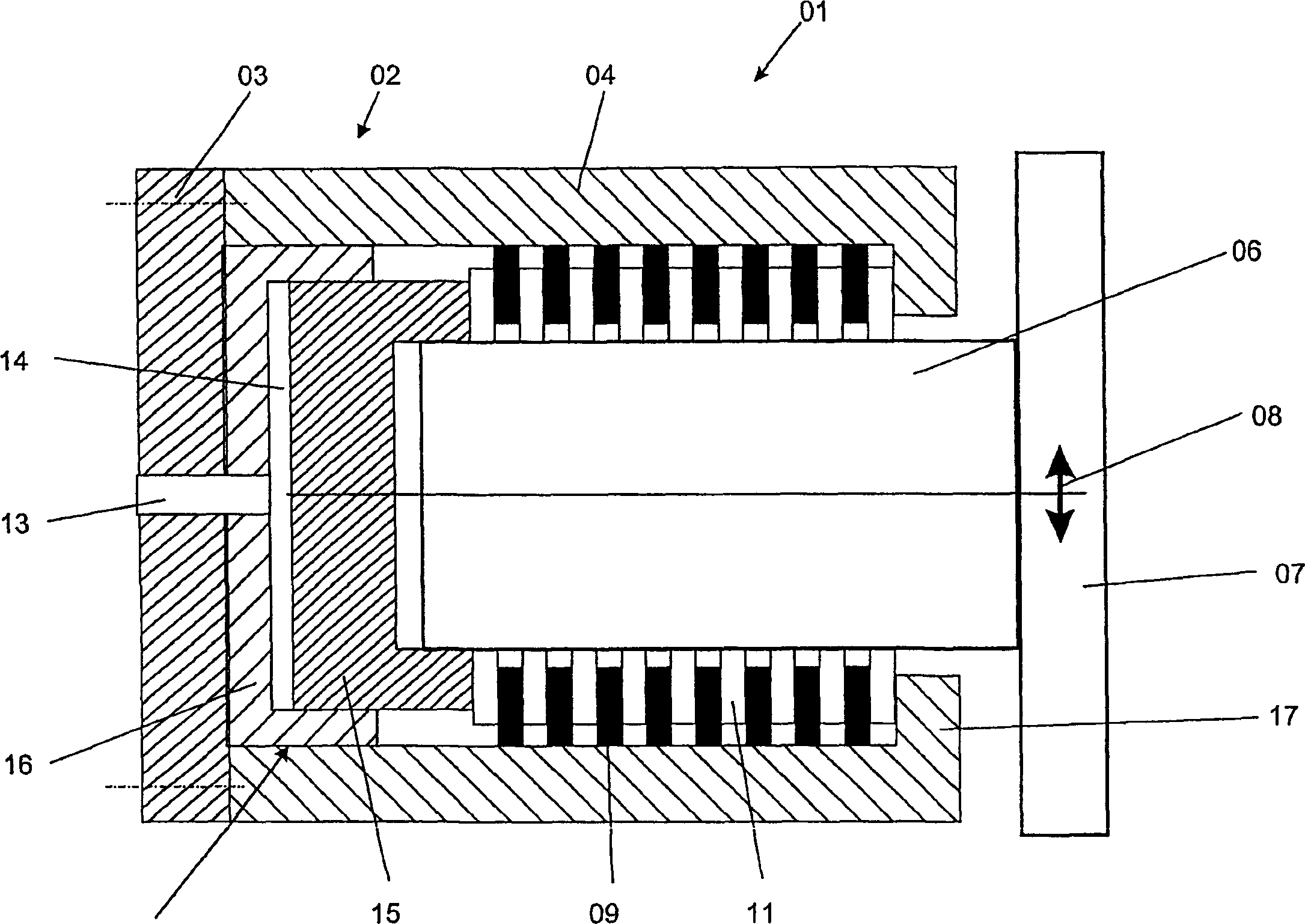
[0033] exist figure 1 The fixing device 01 shown in has a part, for example a base body 02, said base body is made up of a cover 03 and a sleeve 04, and a part arranged movably in the sleeve 04, for example a peg 06, There is a fixed plate 07 on the outside of the peg. The base body 02 is fixed on a frame, for example, and a roller fixing pin for setting the roller is fixed on the fixing plate 07 by screws, for example.

[0034] There is a certain clearance between the peg 06 and the sleeve 04 in the radial direction, so that the peg 06 can move in any direction 08 corresponding to the base 02 on the adjustment plane extending perpendicular to the drawing. The fastening plate 07 can thus be moved, for example, in the direction of the upward or downward movement arrow 08 . Moreover, since the fixing device 01 has a circularly symmetrical structure, adjustment movement in any other direction within the adjustment plane can also be realized. On the inner side of the sleeve 04 ...


PUM


Abstract

The invention relates to a fixing device for clamping two radially displaceable elements.

Description

technical field [0001] The invention relates to a fastening device for fastening a device having at least two components which are relatively movable in an adjustment direction. Background technique [0002] A typical printing press, such as a rotary printing press, has a plurality of rollers, in particular inking rollers, which are used to transfer the ink in the ink cartridge to the plate cylinder. The dosing of the ink adhering to the printing plate cylinder is realized by the ink roller, so as to realize the ink transfer as a standard film of a certain thickness. Compensation for disturbances such as speed changes and rotational vibrations can thus be achieved. [0003] In addition, dampening rollers are provided in the printing press, which serve to transfer a dampening agent, such as water, to the printing unit. [0004] Usually, the roller pair is formed by contacting rollers, at least one of which has a roller surface made of elastic material, so that this roller s...

Claims


Application Information

Patent Timeline
IPC IPC(8): B41F7/40B41F13/24B41F31/30F16C13/02F16C23/02F16D63/00F16D65/14
CPCF16C13/02F16D2121/02F16D63/00F16C23/02B41F13/24B41F31/30
Inventor 贝恩德·克劳斯·法伊斯特沃尔夫冈·奥托·雷德尔格奥尔格·施奈德
Owner KOENIG & BAUER AG
Learn More