Fuse element assembly

A technology for fuse elements and components, applied in electrical components, circuits, emergency protection devices, etc., can solve the problems of complex components, inability to overcome the problem of jetting, the final damage of fuse lines, and increasing the physical size of full-scale fuses.

Inactive Publication Date: 2005-09-14
COOPER UK LTD
View PDF0 Cites 0 Cited by
  • Summary
  • Abstract
  • Description
  • Claims
  • Application Information

AI Technical Summary

Problems solved by technology

While reinforcement of the insulating sleeve of the first portion of the fuse element assembly is of some use in producing higher current and voltage ratings for full-range fuses, reinforcement of the sleeve tends to complicate the assembly and increase the manufacturing cost of the fuse, Cannot overcome the problem of excessive ionized gas jetting and eventual damage during fuse operation
[0006] In addition, although the rated current and rated voltage of a full-range fuse can be increased by using a fuse element and a fuse structure with a larger cross-sectional area and capacity, this also increases the physical size of the full-range fuse
Especially when a large number of fuses are used, the increase in fuse size is very problematic

Method used


Image

  • Fuse element assembly
  • Fuse element assembly
  • Fuse element assembly

Examples


Embodiment Construction

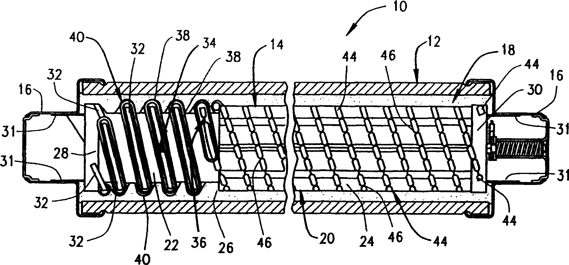
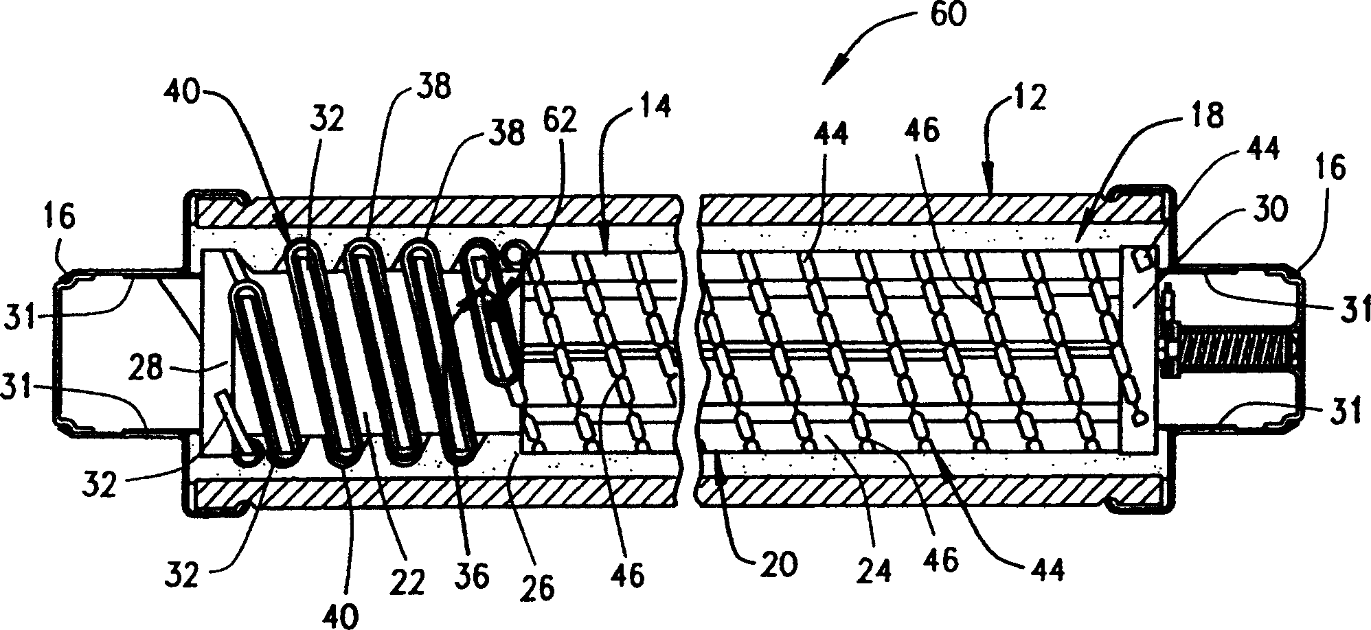
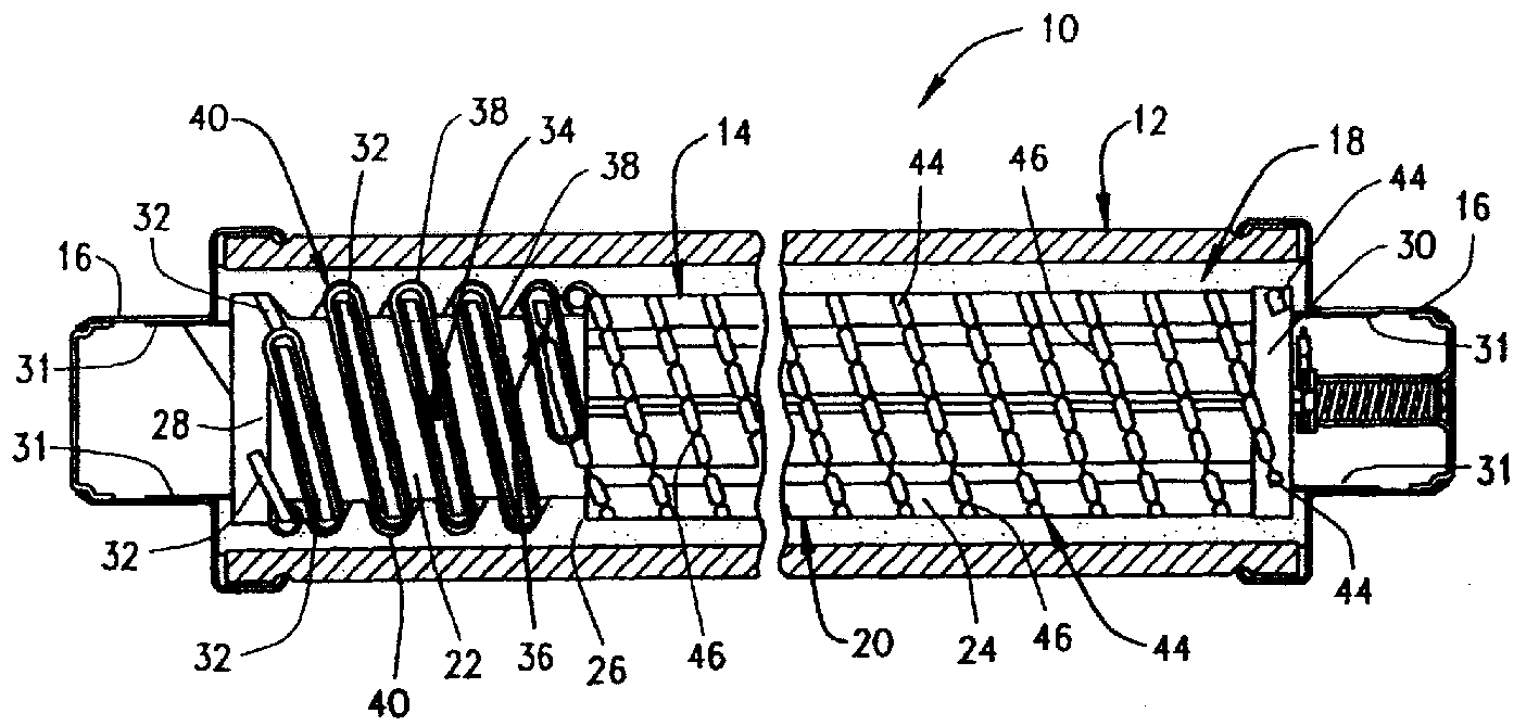
[0014] figure 1 The illustrated full range fuse 10 includes an insulating fuse body 12, a fuse element assembly 14 within the body 12, a conductive end cap 16 coupled to the closed body 12 and electrically connected to the fuse element assembly 14, and a Arc extinguishing material 18 surrounds the fuse element assembly 14 within the body 12 . Thus, when end cap 16 is connected to an energized circuit (not shown), fuse 10 completes an electrical circuit through fuse element assembly 14 . When the current flowing through the fuse 10 approaches an unacceptable level, the fuse element assembly 14 at least partially operates, melts, vaporizes, or opens, depending on the characteristics of the fuse element assembly 14 and thus the current rating of the fuse 10 , thereby limiting the current and interrupting the damaging current flowing through the fuse 10, as detailed below. Therefore, the circuit and equipment on the connection side can be electrically isolated from the faulty lo...


PUM


Abstract

A Full-Range fuse element assembly includes an insulative former having opposite first and second ends and electrically conducting connectors coupled to ends of the former. A plurality of fuse elements extend between the first connector and the second connector about the insulative former, and each of the fuse elements include a low current interrupting fuse element portion extending from the first connector and a high current limiting fuse element portion extending from the second connector. An insulative sleeve surrounds each of the low current interrupting fuse element portions, and each sleeve includes an end adjacent a respective one of the high current limiting fuse element portions. Each of the low current interrupting fuse element portions includes a weak spot located proximate the second end of a respective one of the sleeves.

Description

technical field [0001] The present invention relates generally to a fuse element or link assembly, and more particularly to a fuse element assembly for a general purpose or full range fuse. Background technique [0002] Fusible links are widely used as overcurrent protection devices to prevent damage to circuits. Fusible link terminals generally form an electrical connection between a power source and an electronic component or group of components distributed in an electrical circuit. One or more fusible links or elements, or fuse element assemblies, are connected between the fuse terminals so that when the current through the fuse exceeds a predetermined limit, the fusible element melts or one or more fuses are disconnected through the fuse. circuit to avoid damage to electronic components. [0003] General purpose or full range high voltage current limiting fuses can safely interrupt higher fault circuits as lower fault circuits with equal efficiency. At least one type ...

Claims


Application Information

Patent Timeline
Patent Type & Authority Patents(China)
IPC IPC(8): H01H85/042H01H85/055H01H85/10H01H85/12H01H85/18
CPCH01H85/185H01H85/12H01H2085/383H01H85/055H01H85/10H01H85/042
Inventor 哈罗德·约翰·汉德科克马克·保罗·贾德森
Owner COOPER UK LTD
Why Eureka
Try Eureka