Filter device for microfiltration of oil

A filter device and micro-filtration technology, which is applied in the direction of filtration separation, membrane filter, cartridge filter, etc., can solve problems such as device damage

Inactive Publication Date: 2005-10-26
NTZ INT HLDG
View PDF1 Cites 2 Cited by
  • Summary
  • Abstract
  • Description
  • Claims
  • Application Information

AI Technical Summary

Problems solved by technology

Although this phenomenon occurs only briefly, it still represents a non-negligible disadvantage of the above-mentio

Method used


Image

  • Filter device for microfiltration of oil
  • Filter device for microfiltration of oil
  • Filter device for microfiltration of oil

Examples


Embodiment Construction

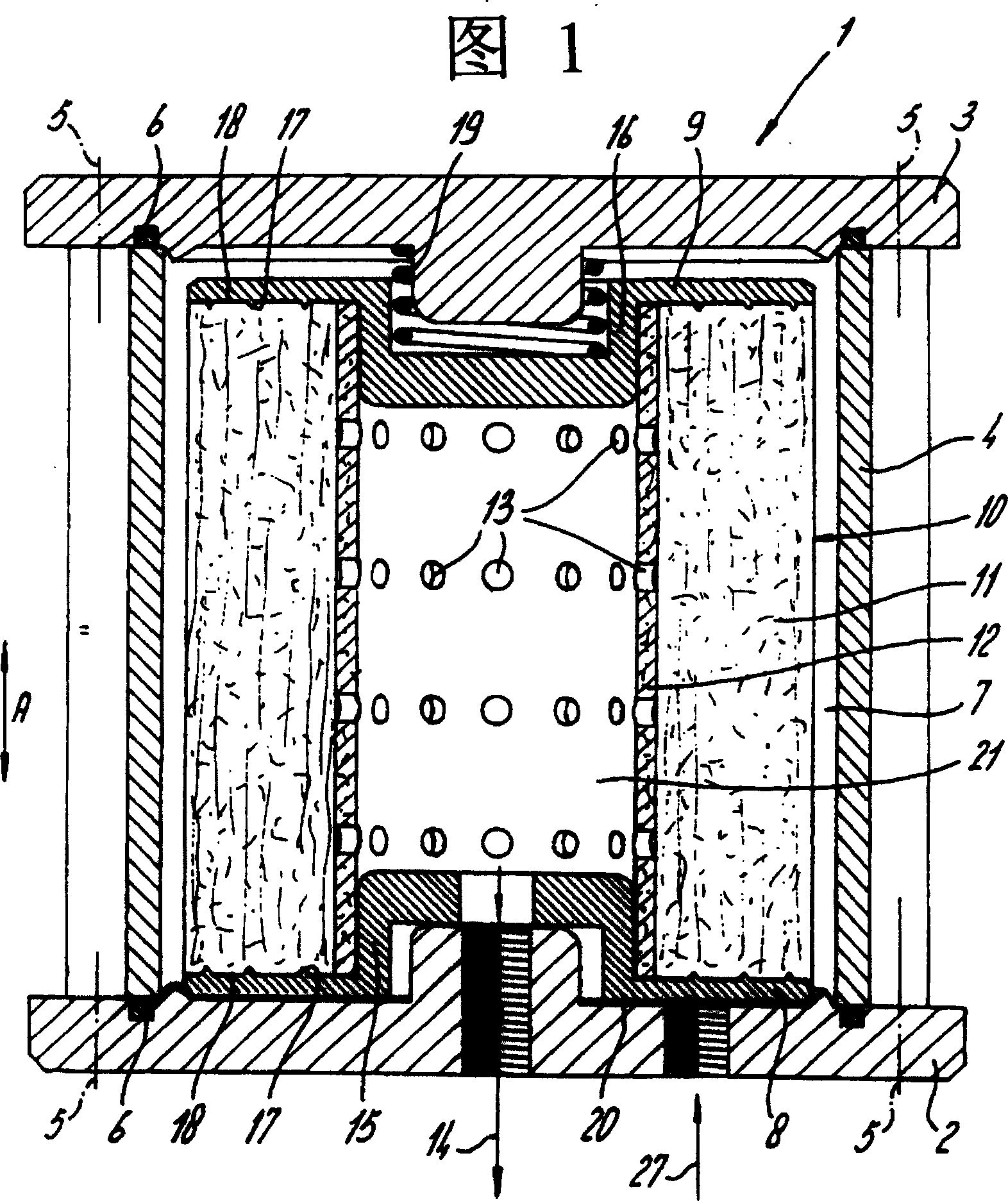
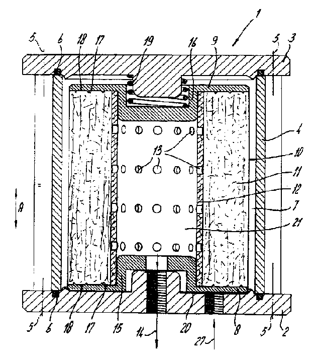
[0020] The filter device 1 according to the invention comprises a filter housing formed by a bottom plate 2, a top plate 3 and a cylindrical wall 4 located between the plates. Wherein the bottom plate 2 and the top plate 3 are connected to the cylindrical wall 4 by means of screws, which are schematically indicated by the axis 5 in the figure. To ensure a seal between the bottom plate 2 and the cylindrical wall 4 and between the top plate 3 and the cylindrical wall 4 , O-ring seals 6 are provided.

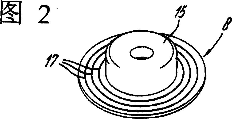
[0021] Inside the filter housing, there is a first or bottom sealing element 8 and a second or top sealing element 9 tightly mounted on the bottom plate 2 by means of drill-through hollow bolts provided with two sealing rings. A filter insert 10 is arranged between the end sealing elements 8 and 9 . The filter element 10 comprises filter paper 11 wound on a wound core 12, which may also comprise a large number of layers of tissue paper. The winding core 12 is provided with holes ...


PUM


Abstract

The invention relates to a filter device for microfiltration of oil, in particular for use in engines, automatic transmissions and hydraulic applications. The filter device comprises a tubular microfilter cartridge through which medium can flow in the transverse direction and which has open ends. This filter cartridge is accommodated in a filter chamber which is enclosed by a filter housing and is accommodated between two end closure elements, between which the filter cartridge is clamped under prestress. On their surface facing towards the filter cartridge the end closure elements are provided with at least one rib which extends in the transverse circumferential direction of the filter cartridge. The holding means comprise a spring which acts with prestress on one of the end closure elements, in such a manner that his closure element follows the end wall which it adjoins in the event of longitudinal expansion and also in the event of longitudinal contraction.

Description


Claims


Application Information

Patent Timeline
Owner NTZ INT HLDG
Why Eureka
Try Eureka