Heat transferring tube for downward flow fluid membrane distiller

A heat transfer tube and liquid film technology, which is applied in vertical tube evaporators, evaporation, tubular elements, etc., can solve the problems of reduced heat transfer performance of heat transfer tubes.

Inactive Publication Date: 2005-11-23
KOBE STEEL LTD
View PDF1 Cites 0 Cited by
  • Summary
  • Abstract
  • Description
  • Claims
  • Application Information

AI Technical Summary

Problems solved by technology

In these areas, the heat transfer performance of the heat transfer tube is reduced due to the inability to exchange heat between the refrigerant and the water in the tube.

Method used


Image

  • Heat transferring tube for downward flow fluid membrane distiller
  • Heat transferring tube for downward flow fluid membrane distiller
  • Heat transferring tube for downward flow fluid membrane distiller

Examples


Embodiment

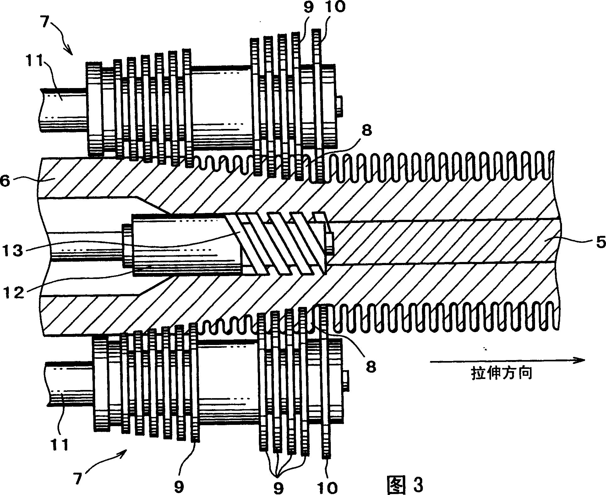
[0055] Hereinafter, the effect of the embodiment of the present invention will be specifically described in comparison with comparative examples outside the scope of the claims. First, the test methods common to the following test examples will be explained. First, the method of measuring the total heat transfer coefficient of the heat transfer tube as the heat transfer performance of the heat transfer tube is explained. Figure 4 It is a schematic diagram showing the configuration of the test device used in the heat transfer tube performance evaluation test of the embodiment of the present invention and the comparative example.

[0056] Such as Figure 4 As shown, a cavity 14 is provided in the test device, and the inside of the cavity 14 is divided by a partition wall 15 into two chambers of an evaporator 14a and an absorber 14b. In addition, steam can flow through the upper portion of the partition wall 15. In the evaporator 14a, the four heat transfer tubes 16 are arranged in ...


PUM

PropertyMeasurementUnit
heightaaaaaaaaaa
heightaaaaaaaaaa
heightaaaaaaaaaa

Abstract

The present invention provides a heat transfer tube for a falling film type evaporator, in which water spreading characteristics, particularly the water spreading characteristics in the tube axis direction, enhancing the heat transfer ability. Three types of projections 2, 3, and 4 are formed on an external surface 1a of a heat transfer tube body 1. A respective plurality of projections 2 to 4 are arranged spirally in parallel to one another, forming projection groups 2a to 4a. The number of each projection group 2 to 4 is one. Pitches P2 to P4 for the projections 2 to 4 are in the range of 0.35 mm<=P4 F28F 1 / 42 9 17 0 2002 / 6 / 12 1391080 2003 / 1 / 15 1228603 2005 / 11 / 23 2005 / 11 / 23 2005 / 11 / 23 Kobe Steel Ltd. Japan Ota Yoshio Saiki Chikara Takahashi Hiroyuki wang huimin 11021 The Patent Agency of the Chinese Academy of Sciences Inside the Chinese Academy of Sciences, No.52 Sanlihe Road, Fuwai, Beijing 100864 Japan 2001 / 6 / 12 2001-177516

Description

Technical field [0001] The present invention relates to a downward-flowing liquid that allows a refrigerant to flow down to the outer surface of a tube, forms a liquid film on the outer surface of the tube, and evaporates the refrigerant, thereby performing heat exchange with a fluid flowing through the tube. Heat transfer tube for film evaporator. Background technique [0002] The absorption cryogenic water machine is a refrigeration cycle system, equipped with: an absorber that makes the absorption liquid (such as lithium bromide aqueous solution) absorb the vapor of the refrigerant (such as water); a regenerator that extracts the refrigerant vapor from the above-mentioned absorption liquid; condensation The condenser for the extracted refrigerant and the evaporator for evaporating the condensed refrigerant and performing heat exchange. The feature of the absorption cryogenic water machine is that it does not use refrigerants with high warming coefficients such as chlorofluoroc...

Claims


Application Information

Patent Timeline
Patent Type & Authority Patents(China)
IPC IPC(8): B01D1/06B21D17/04F28F1/42
CPCF28F1/422F28F1/42B01D1/065
Inventor 多田义男佐伯主税高桥宏行
Owner KOBE STEEL LTD
Why Eureka
Try Eureka