

Embedded hub vortex compressor
A scroll compressor, embedded technology, applied in the field of scroll compressors, can solve the problems of uneven force on the scroll, poor sealing state, large eccentric wear on the scroll working surface, etc.
- Summary
- Abstract
- Description
- Claims
- Application Information
AI Technical Summary
Problems solved by technology
Method used
Image

Examples
Embodiment Construction
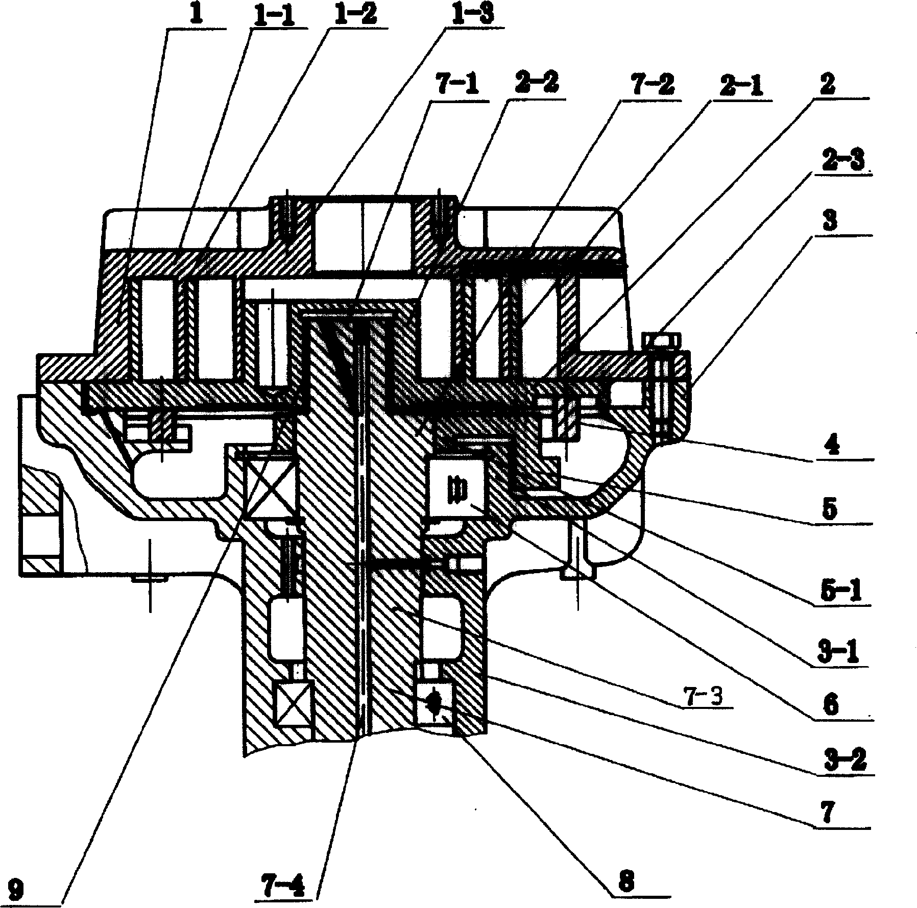
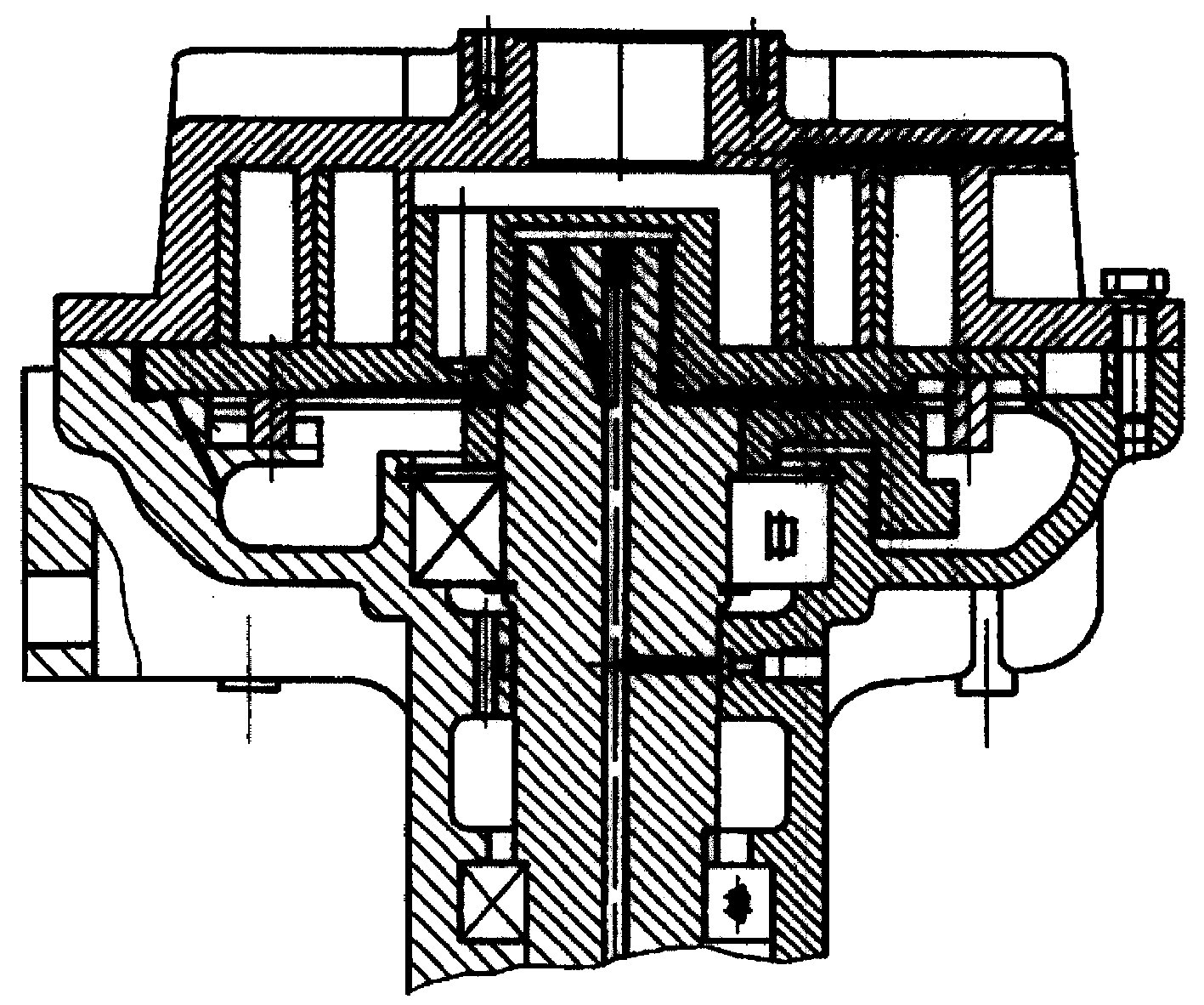
[0008] Such as figure 1 As shown, the non-revolving scroll 1 is installed on the support body 3, and the first spiral scroll 1-2 protrudes downward from the end plate 1-1, and 1-3 is the hub of the non-revolving scroll 1. The second spiral wrap 2-1 protruding upward from the end plate 2-3 of the scroll member 2 intersects with the first spiral wrap 1-2 to form a plurality of moving fluid chambers. At the central position of the end plate 2-3 of the orbiting scroll 2, there is a hub 2-2 embedded in the cavity of the non-orbiting scroll upwards, and the outer circular wall of the hub 2-2 is perpendicular to the end plate of the orbiting scroll 2 The height of the plane where 2-3 is located is smaller than the height of the second spiral scroll 2-1.
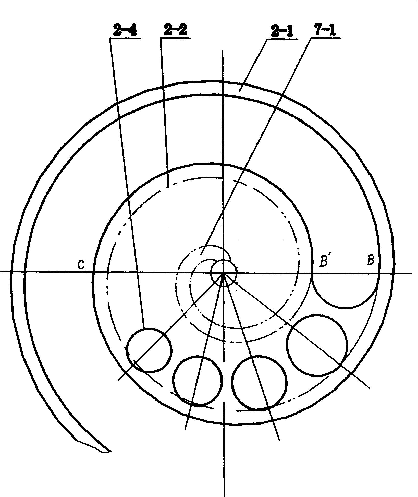
[0009] Such as figure 2 As shown, the projection of the hub 2-2 in the horizontal direction is a spiral, where the BB' arc is the projection of the starting end of the hub in the horizontal direction, the B'C arc is the projectio...
PUM
 Abstract
Description
Claims
Application Information