Braker of electric opening device

A technology of opening device and braking device, applied in the direction of automatic brake, brake type, other opening mechanism, etc., can solve the problem of unable to obtain braking force and so on

Inactive Publication Date: 2006-01-18
TSUDAKOMA KOGYO KK
View PDF1 Cites 2 Cited by
  • Summary
  • Abstract
  • Description
  • Claims
  • Application Information

AI Technical Summary

Problems solved by technology

Therefore, for each heald frame, in addition to not being able to obtain sufficient braking force, due to the difference in size between the components caused by the degree of wear and tear, the crimping force only acts relatively strongly on a part of the heald frames, resulting in insufficient braking force. moving heald frame

Method used


Image

  • Braker of electric opening device
  • Braker of electric opening device
  • Braker of electric opening device

Examples


Embodiment Construction

[0035] Embodiment of the invention

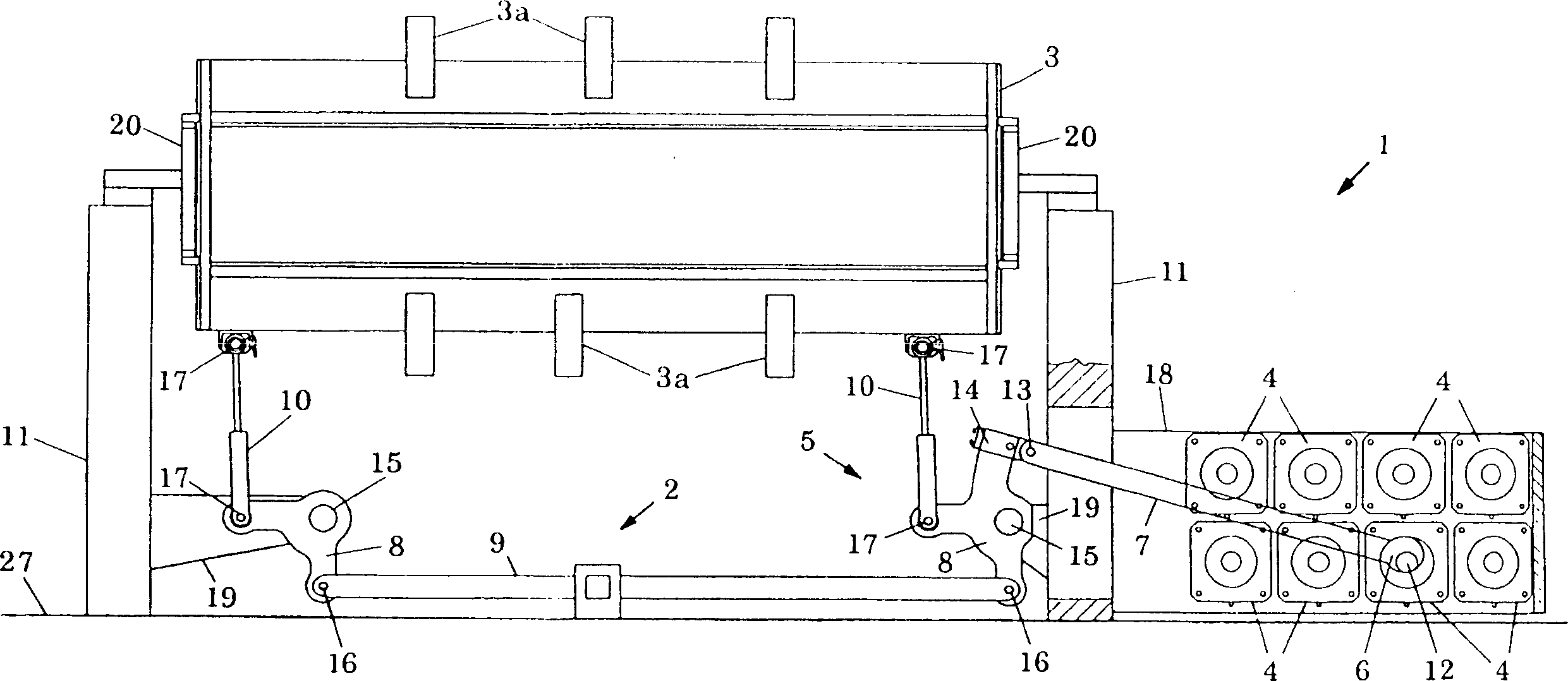
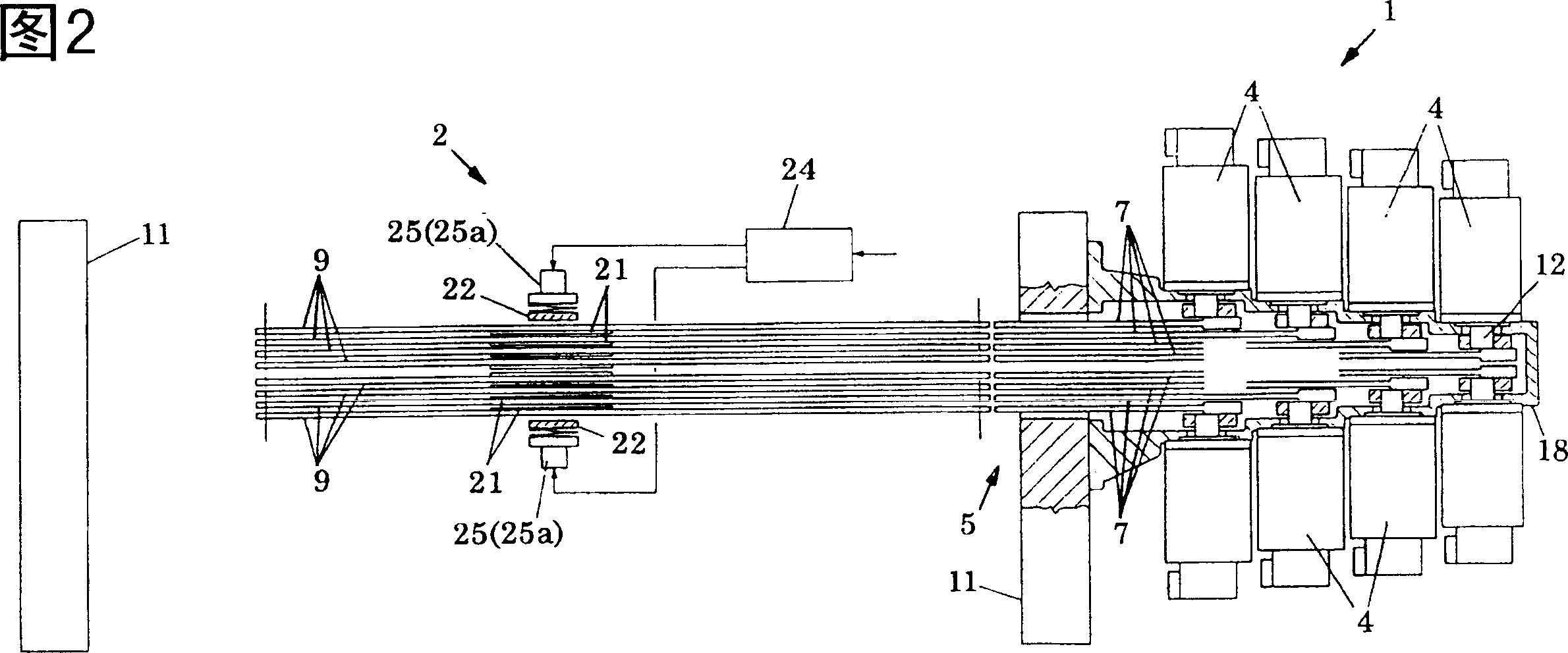
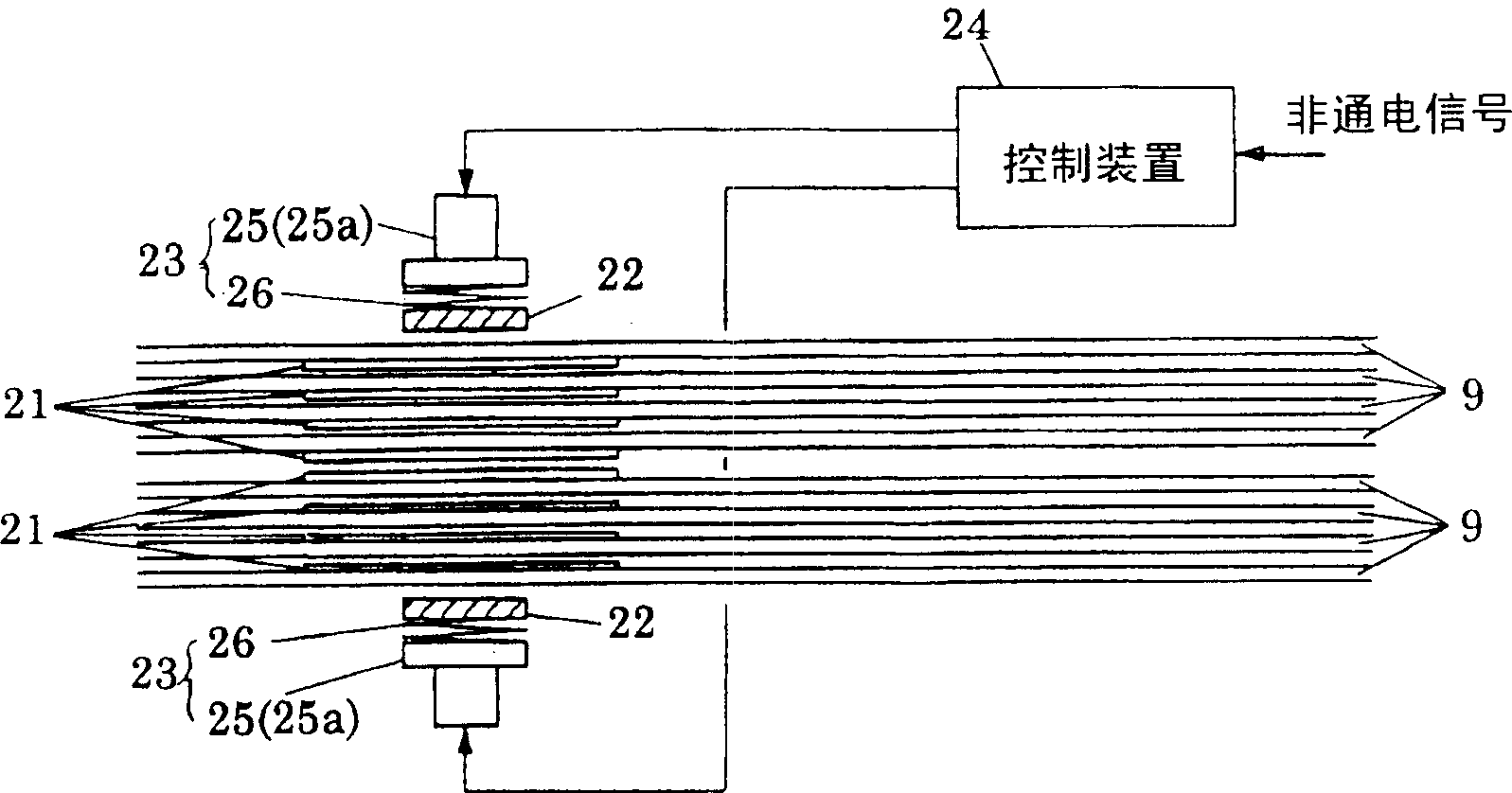
[0036] Figure 1 to Figure 3 It shows the state where the brake device 2 of the electric opening device according to the present invention is assembled to the electric opening device 1 . In the electric shedding device 1 , a plurality of, for example, 16 heald frames 3 are driven by respective drive motors 4 and shedding motion systems 5 to perform shedding motion. The shedding motion system 5 converts the rotary motion of the driving motor 4 into a reciprocating linear motion along the shedding direction, so as to transmit it to the corresponding heald frame 3, which consists of an eccentric shaft 6, a swing rod 7, a pair of driving levers 8, a connecting member 9, The driving rod 10 and the like are constituted.

[0037] 8 drive motors 4 are arranged on the outside of one of the loom frames 11 in a pair of loom frames 11 in a group of 8 by means of brackets 18, and the eccentric shafts 6 of each output shaft 12 , swing bar 7, connectin...


PUM


Abstract

The present invention provides a kind of electrically shedding device, which can avoid decent of heald frame in case of power failure of the driven motor to prevent damage of the heald frame and the warp. The electrically shedding device has shedding motion systems for the heald frames, and the shedding motion systems move to set press jointing members repeatedly and one pair of opposite holding members in the position capable of holding these press jointing members. At least on of the pair of holding members is provided with a driving part driving the holding member towards the press jointing direction. In power failure of the drive motor, the driving part acts to drive the holding members to move towards the holding direction, so that all the press jointed members are held between two holding members to maintain the heald frames against their motion.

Description

technical field [0001] The present invention relates to a device for preventing heald frames from moving when the driving motor is not powered by braking force in an electric shedding device of a loom. Background technique [0002] Japanese Unexamined Publication No. 10-298843 discloses a braking device for a heald frame of a loom. This brake device for a heald frame of a loom has a brake device at a position corresponding to side stays forming left and right end faces of a plurality of heald frames. During the operation of the loom, due to a power failure or a failure of the electrical system, when the motor is in a non-energized state, the brake device presses the brake pads to the side of the side stay, and stops multiple heald frames by using frictional braking force. The movement of the heald frame prevents the heald frame from falling and out of control, and prevents the damage of the heald frame and the damage of the warp. [0003] A plurality of heald frames are ar...

Claims


Application Information

Patent Timeline
Patent Type & Authority Patents(China)
IPC IPC(8): D03C13/00F16D59/02
Inventor 平井淳
Owner TSUDAKOMA KOGYO KK
Why Eureka
Try Eureka