Sample component analysis system and sensor chip and sensor pack used for the system

A sensor chip and component analysis technology, which is applied in the direction of analyzing materials, using chemical indicators to analyze, and analyzing materials through optical means, can solve problems such as failure, overall size increase, and cost increase.

Inactive Publication Date: 2006-04-05
OMRON HEALTHCARE CO LTD
View PDF0 Cites 0 Cited by
  • Summary
  • Abstract
  • Description
  • Claims
  • Application Information

AI Technical Summary

Problems solved by technology

[0005] However, in this case, the analytical instrument has a complex mechanism, which produces malfunctions
Moreover, it will lead to an increase in the overall size and an increase in cost

Method used


Image

  • Sample component analysis system and sensor chip and sensor pack used for the system
  • Sample component analysis system and sensor chip and sensor pack used for the system
  • Sample component analysis system and sensor chip and sensor pack used for the system

Examples


no. 2 example

[0138] Figure 4 An analytical instrument 41 and a sensor pack 2 of the second embodiment of the present invention are shown.

[0139] The same components or parts as those in the first embodiment are denoted by the same reference numerals, and descriptions thereof are omitted.

[0140] The structures of the sensor pack 2 and the sensor chip 3 in this embodiment are the same as those in the first embodiment.

[0141] The structures of the fixing member 13 and the connection electrode 14 of the analytical instrument 41 are the same as those of the first embodiment. In this embodiment, however, one support 42 can be opened and closed by moving relative to the body of the analytical instrument 41 .

[0142] The supporting member 42 is connected to the main body of the analyzing instrument 41 by a hinge or the like so as to be swingable along a plane perpendicular to the insertion direction of the sensor pack 2 . As in the first embodiment, a pair of guide portions 23, 23 are f...

no. 3 example

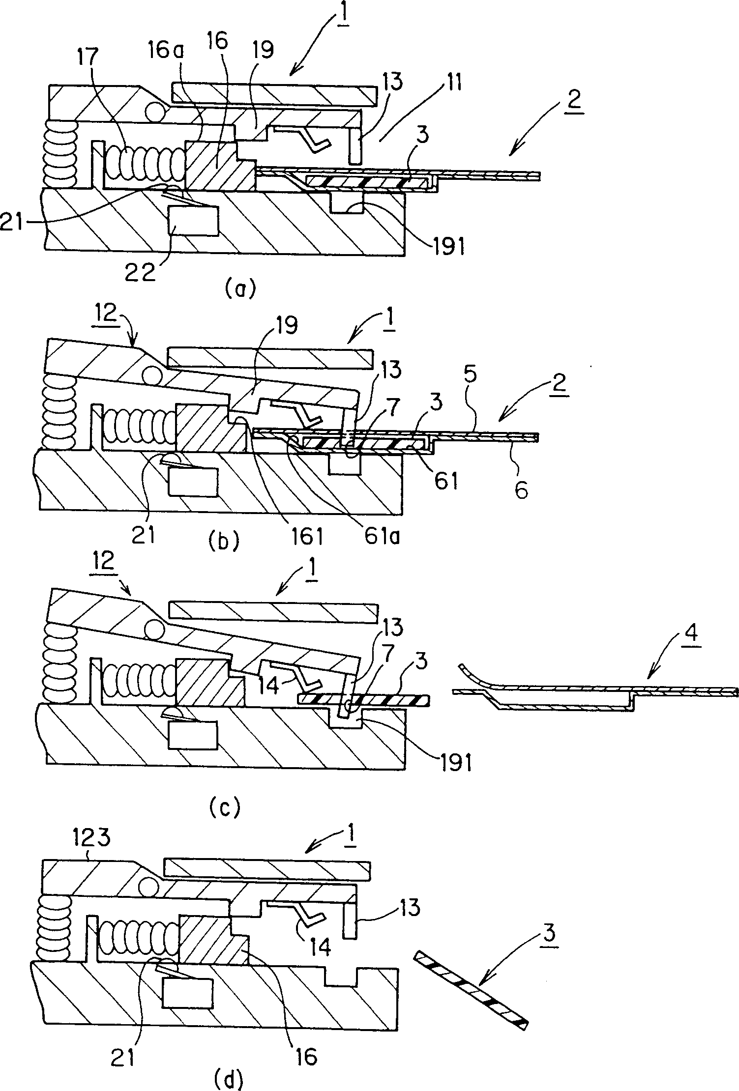
[0149] Figure 5 (a) to 5(d) show an analyzing instrument 51 and a sensor pack 52 of the third embodiment of the present invention.

[0150] The same components or portions in this embodiment as those in the first embodiment are denoted by the same reference numerals, and descriptions thereof are omitted.

[0151] In this embodiment, one groove 53 is formed in one side of the analyzer 51 , and the sensor pack 52 is inserted into the groove 53 in the direction of the arrow and the sensor chip 3 is disposed through the groove 53 .

[0152] Figure 5 (a) shows the overall structure of the analyzer 51 and the sensor pack 52 . Figure 5 (b) is a top view of the analytical instrument 51, Figure 5 (c) is from Figure 5 (b) is a side view looking from the underside, while Figure 5 (d) is from Figure 5 A side view when looking from the right side of (b). These views only show the basic parts and the external structure of the analytical instrument 51, and do not show other com...

no. 5 example

[0171] Figure 7 An analytical instrument 1 and a sensor pack 70 of a fifth embodiment of the present invention are shown.

[0172] The same components or parts as those in the first embodiment are denoted by the same reference numerals, and descriptions thereof are omitted.

[0173] In this embodiment, the sensor package 70 has the same sensor chip housing structure as in the first embodiment. In the sensor pack 70, ends of a plurality of sensor chip housing parts 72 opposite to the insertion side are connected by a connection part 71, and the sensor chip 3 is housed in each housing extending from the connection part 71 like comb teeth. Section 72. The analytical instrument 1 also has basically the same structure as that of the first embodiment. However, in this embodiment, the analytical instrument 1 differs from the first embodiment in that the sides where the opening 11 is formed are cut away in the horizontal direction at their ends opposite to each other in order to a...


PUM


Abstract

A sample ingredient analyzing system, and a sensor pack and a sensor chip usable in the system. The analyzing system has an analyzing device of a simple structure to which the sensor chip can be easily attached. The sensor pack containing the sensor chip is inserted into an opening of the analyzing device. When a slider is pushed in by the sensor pack, a supporting member rotates and a retaining member penetrates a film and plunges through a hole in the sensor chip. When the packaging material of the sensor pack is drawn out, only the sensor chip is retained by the retaining member. When a button is pressed, the supporting member rotates to release the retaining member from the retaining state, thereby enabling the sensor chip to be thrown away.

Description

technical field [0001] The invention relates to a sample component analysis system, which includes a sensor chip and an analysis instrument, and relates to a sensor chip and a sensor outer box used in the system. More specifically, the present invention relates to an improved system for manipulating sensor chips used in an analysis process to qualify or quantify glucose or other constituents in specific constituents in blood or industrial products, food, etc. Background technique [0002] using a method such as Figure 33 A sample component analysis system for the sensor chips shown in (a) and 33(b) is known. That is, a sensor chip 700 is taken out from a packaging material 701 made of aluminum or the like and is manually set in an analysis instrument 702, and a sample is supplied to a reaction part 700a on the sensor chip 700, for example, by dropping on the reaction part 700a. The analysis is performed on the part 700a. [0003] In such a system, it is necessary to remov...

Claims


Application Information

Patent Timeline
Patent Type & Authority Patents(China)
IPC IPC(8): G01N27/26G01N31/22G01N35/00G01N37/00
CPCG01N35/00029G01N33/48757G01N21/8483G01N31/22
Inventor 时田宗雄佐野佳彦九鬼清次田中伸哉
Owner OMRON HEALTHCARE CO LTD
Why Eureka
Try Eureka