

Rotor of permanent magnet type rotary electric machine and mfg. method thereof
A technology of permanent magnets and rotating electrical machines, applied in the direction of magnetic circuit rotating parts, manufacturing stator/rotor body, magnetic circuit shape/style/structure, etc. The effect of concentration and improvement of close contact
- Summary
- Abstract
- Description
- Claims
- Application Information
AI Technical Summary
Problems solved by technology
Method used
Image

Examples
no. 1 Embodiment
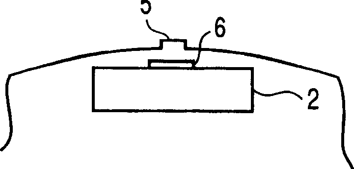
[0071] Figure 2A , 2B , , and 2C are radial cross-sectional views showing an example of a method for manufacturing a rotor for a permanent magnet type rotating electrical machine of this embodiment and a rotor for a permanent magnet type rotating electrical machine manufactured by this method.
[0072] and Figure 1A and 1B The same symbols are used for the same parts, and their descriptions are omitted, and only the different parts will be described here.
[0073] In the present embodiment, the rotor of the above-mentioned permanent magnet type rotating electrical machine is manufactured as follows. The rotor of this permanent magnet type rotating electrical machine is composed of a rotor core 1 and a permanent magnet 3. The rotor core 1 is formed by laminating electromagnetic steel sheets. The permanent magnet 3 is installed in the magnet hole 2 provided on the inner peripheral portion of the rotor core 1.
[0074] That is, if Figure 2A , 2B , and 2C, a protrusion 5 i...
no. 2 Embodiment
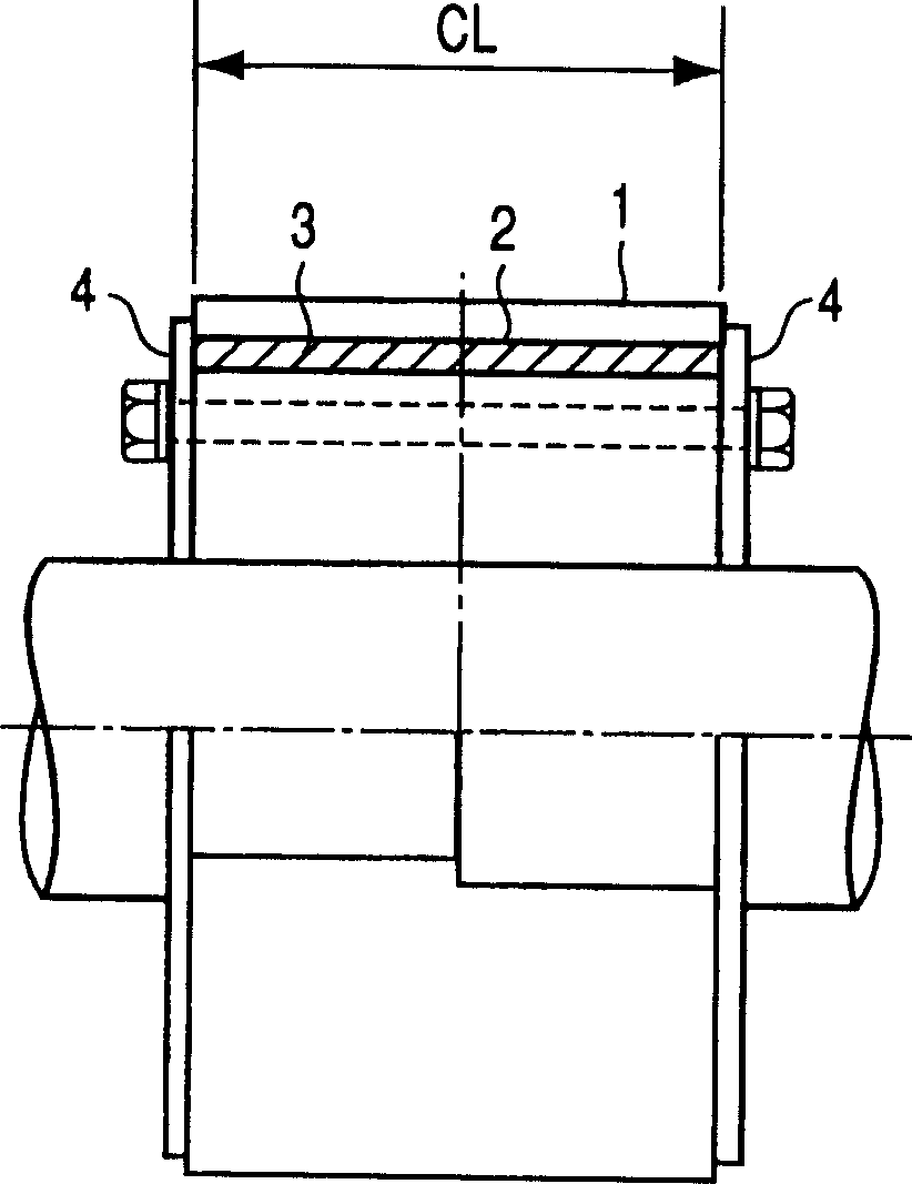
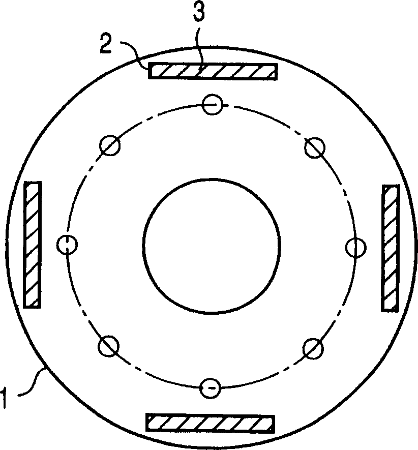
[0091] Figure 3A and 3B A side sectional view and a radial sectional view showing an example of a method for manufacturing a rotor for a permanent magnet type rotating electrical machine of this embodiment and a rotor for a permanent magnet type rotating electrical machine manufactured by this method.
[0092] and Figure 1A and 1B The same symbols are used for the same parts, and their descriptions are omitted, and only the different parts will be described here.
[0093] In the present embodiment, the rotor of the above-mentioned permanent magnet type rotating electrical machine is manufactured as follows. The rotor of this permanent magnet type rotating electrical machine is composed of a rotor core 1 and a permanent magnet 3. The rotor core 1 is formed by laminating electromagnetic steel sheets. The permanent magnet 3 is installed in the magnet hole 2 provided on the inner peripheral portion of the rotor core 1.
[0094] That is, if Figure 3A and 3B As shown, refere...
no. 3 Embodiment
[0103] Figure 4A and 4B A side sectional view and a radial sectional view showing an example of a method for manufacturing a rotor for a permanent magnet type rotating electrical machine of this embodiment and a rotor for a permanent magnet type rotating electrical machine manufactured by this method.
[0104] and Figure 3A and 3B The same symbols are used for the same parts, and their descriptions are omitted, and only the different parts will be described here.
[0105] That is, in the example, as Figure 4A and 4B As shown, in the above-mentioned second embodiment, the rotor cores 1 are stacked, the permanent magnets 3 are inserted, and then the rotor cores 1 are arranged in opposite directions at the positions of both ends of the rotor main body.
[0106] In the method of manufacturing the rotor of the permanent magnet type rotating electrical machine of the above embodiment and the rotor of the permanent magnet type rotating electrical machine manufactured by this ...
PUM
 Abstract
Description
Claims
Application Information