Supercharge Your Innovation With Domain-Expert AI Agents!

Combine harvester heat-sinking and cooling device

A technology of combine harvester and cooling device, applied in the direction of harvesters, cutters, agricultural machinery and implements, etc., can solve the problems of poor maintainability, decreased wind speed, adhesion of dust, etc.

Inactive Publication Date: 2006-04-26
YANMAR CO LTD
View PDF0 Cites 0 Cited by
  • Summary
  • Abstract
  • Description
  • Claims
  • Application Information

AI Technical Summary

Problems solved by technology

[0005] However, the oil cooler of the type in the engine hood and the existing type are all arranged in front of the radiator, so at the back of the oil cooler, the wind speed of the cooling air flowing in from the upper part of the hood is lowered, and it is easy to reduce the speed of the cooling air in the engine hood. Dust is attached to the wind speed lowering part, or the flow of cooling air is obstructed by the oil cooler, and there is a problem that the overall wind speed drops.
[0006] Since these types of oil coolers are all supported on the side of the machine body, the maintenance and repair of the radiator can only be carried out by removing the engine cover and the oil cooler in turn, and there is a problem of poor maintainability.

Method used


Image

  • Combine harvester heat-sinking and cooling device
  • Combine harvester heat-sinking and cooling device
  • Combine harvester heat-sinking and cooling device

Examples


Embodiment Construction

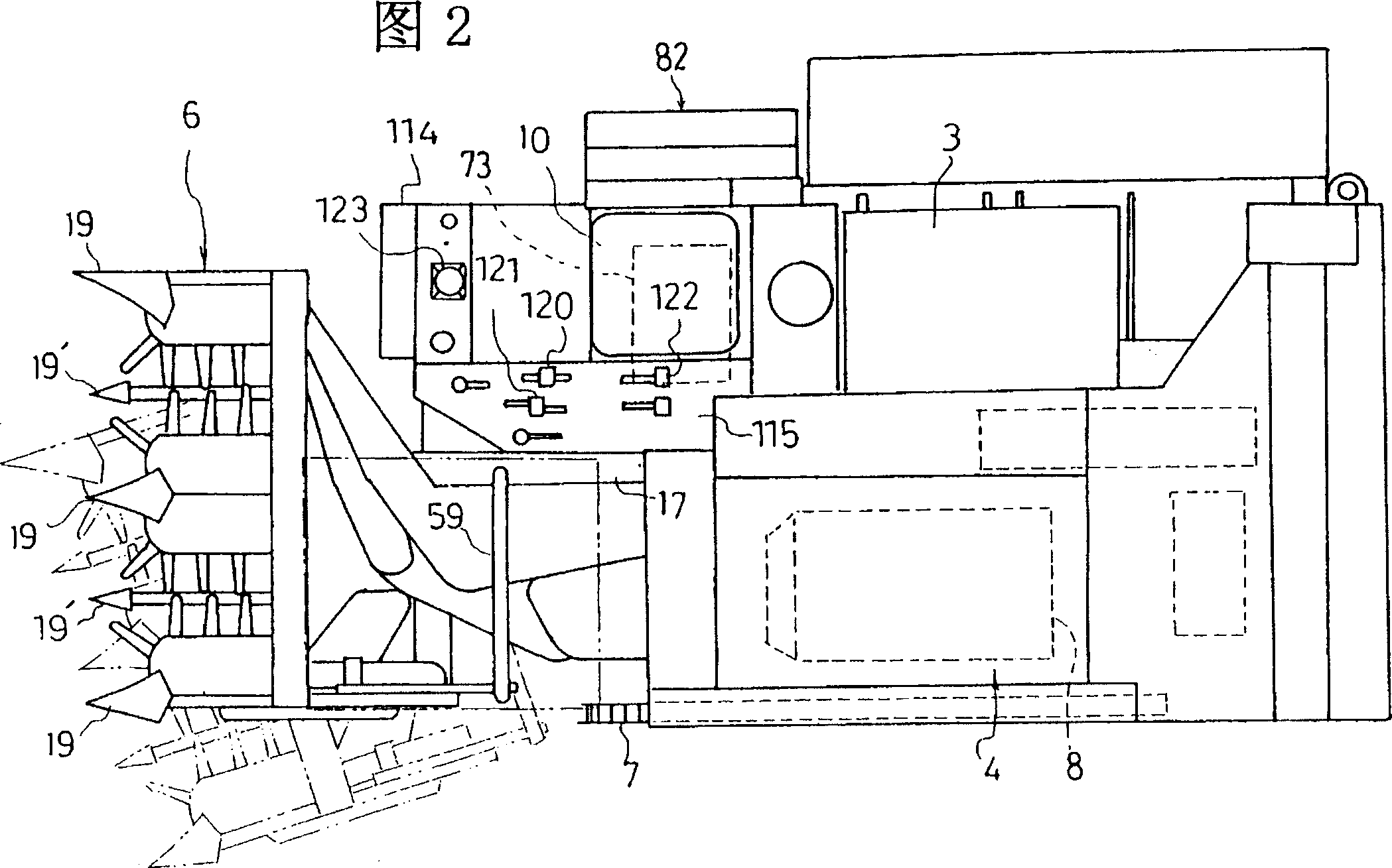
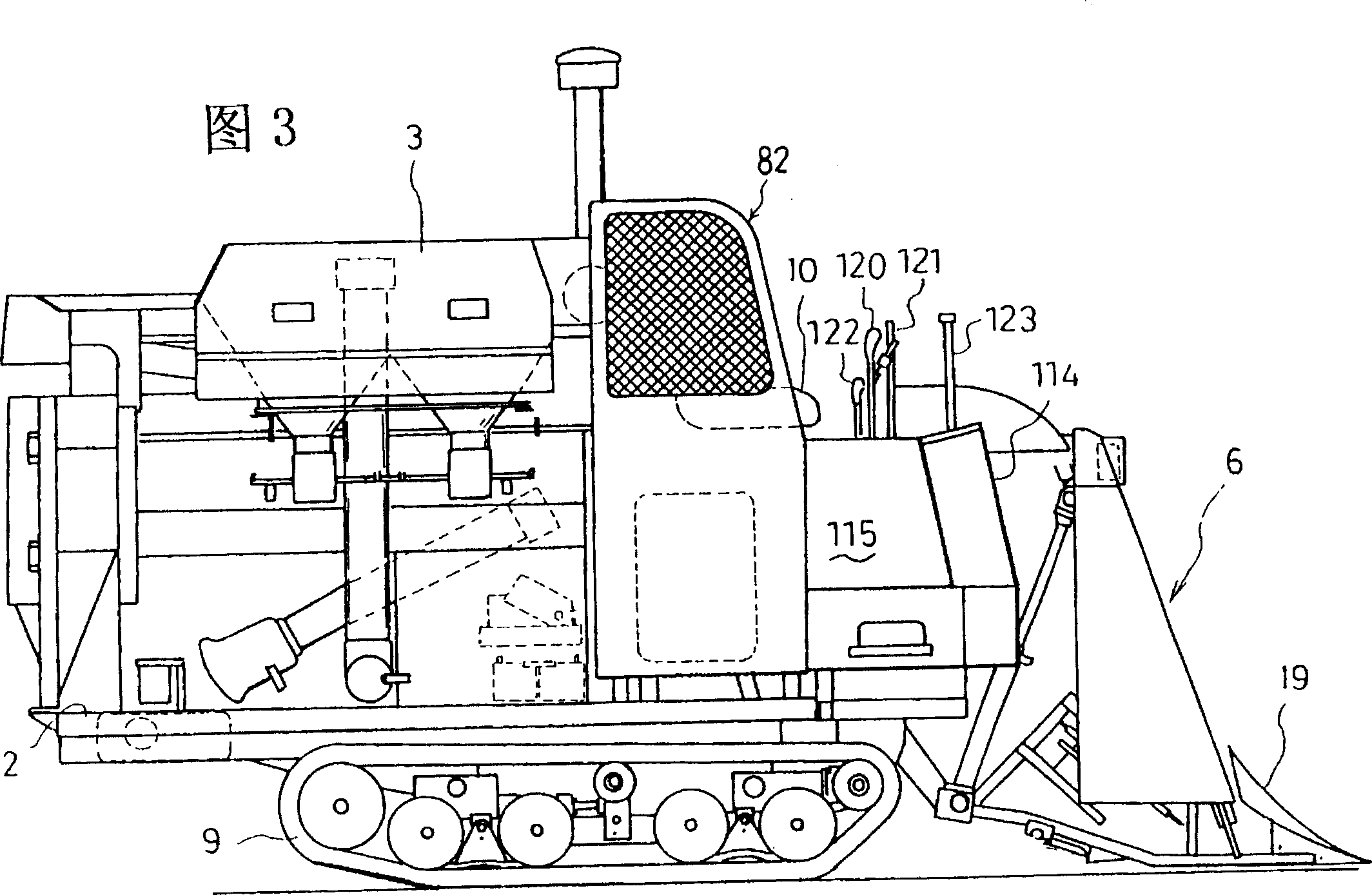
[0014] First, the overall configuration of the combine will be described.

[0015] As shown in Figures 1-3, a frame 2 is installed on the crawler-type traveling device 9, on which, the threshing section 4 and the sorting section 5 are placed on the left side of the body in the direction of travel, and the driver's seat is placed on the right side. 10 and the upper case 3 of storing grain.

[0016] The harvesting unit 6 is located at the forefront of the machine body in front of the threshing unit 4, and each conveying device of the harvesting unit 6 transports the harvested rice straw to the supply chain 7 on the side of the threshing unit 4, and the rice straw transported by the supply chain 7 After being threshed by the threshing drum 8, it is sent to the upper box 3 from the above-mentioned sorting part 5.

[0017] In the frame 2 front portion of above-mentioned driver's seat 10 side, form the mounting table 24 that can support cutting part 6 along up and down rotation, in...


PUM


Abstract

A heat dissipation and cooling device for a combine harvester, an oil cooler 86 is arranged inside the engine cover 82, and the oil cooler 86 is disposed obliquely away from the radiator 74 in the cooling air flow path in the engine cover 82, and the oil cooler 86 can be It turns integrally with the hood 82 . In this way, the cooling air can be made to flow well, dust can be prevented from adhering to the radiator, and maintenance and management of the air filter can be performed easily and quickly.

Description

technical field [0001] The present invention relates to a heat radiation and cooling device for a combine in which an oil cooler is arranged inside an engine hood covering the outside of an engine side radiator. Background technique [0002] In the past, in combine harvesters equipped with hydraulic cylinders for harvesting and lifting and hydraulic continuously variable transmissions (hereinafter referred to as "HST"), etc., due to the large amount of oil used, in order to improve the working efficiency of hydraulic machines and prevent deterioration , equipped with an oil cooler. This oil cooler is disposed on the suction side of a radiator for cooling an engine disposed under a seat. [0003] Since such a conventional oil cooler is directly fixed to the mounting bracket of the radiator, a useless space is generated in a combine harvester of a specification that does not mount the oil cooler, and since the mounting bracket is also large, an increase in unnecessary weight ...

Claims


Application Information

Patent Timeline
IPC IPC(8): A01D41/02A01D41/12
Inventor 赤嶋晋山崎次男草地宽太
Owner YANMAR CO LTD
Features
  • R&D
  • Intellectual Property
  • Life Sciences
  • Materials
  • Tech Scout
  • Unparalleled Data Quality
  • Higher Quality Content
  • 60% Fewer Hallucinations
Learn More