Self-tightening type drill chuck in modified structure

A drill chuck and self-tightening technology, which is applied in the mechanical field, can solve problems such as insufficient reliability and complex structure, and achieve the effects of simple and reasonable structure, loosening and unloading, labor saving, and high practical value

Inactive Publication Date: 2006-07-26
游友民
View PDF0 Cites 0 Cited by
  • Summary
  • Abstract
  • Description
  • Claims
  • Application Information

AI Technical Summary

Problems solved by technology

However, the self-tightening drill chuck also has disadvantages such as relatively complicated structure and insufficient reliability.

Method used


Image

  • Self-tightening type drill chuck in modified structure
  • Self-tightening type drill chuck in modified structure
  • Self-tightening type drill chuck in modified structure

Examples


Embodiment Construction

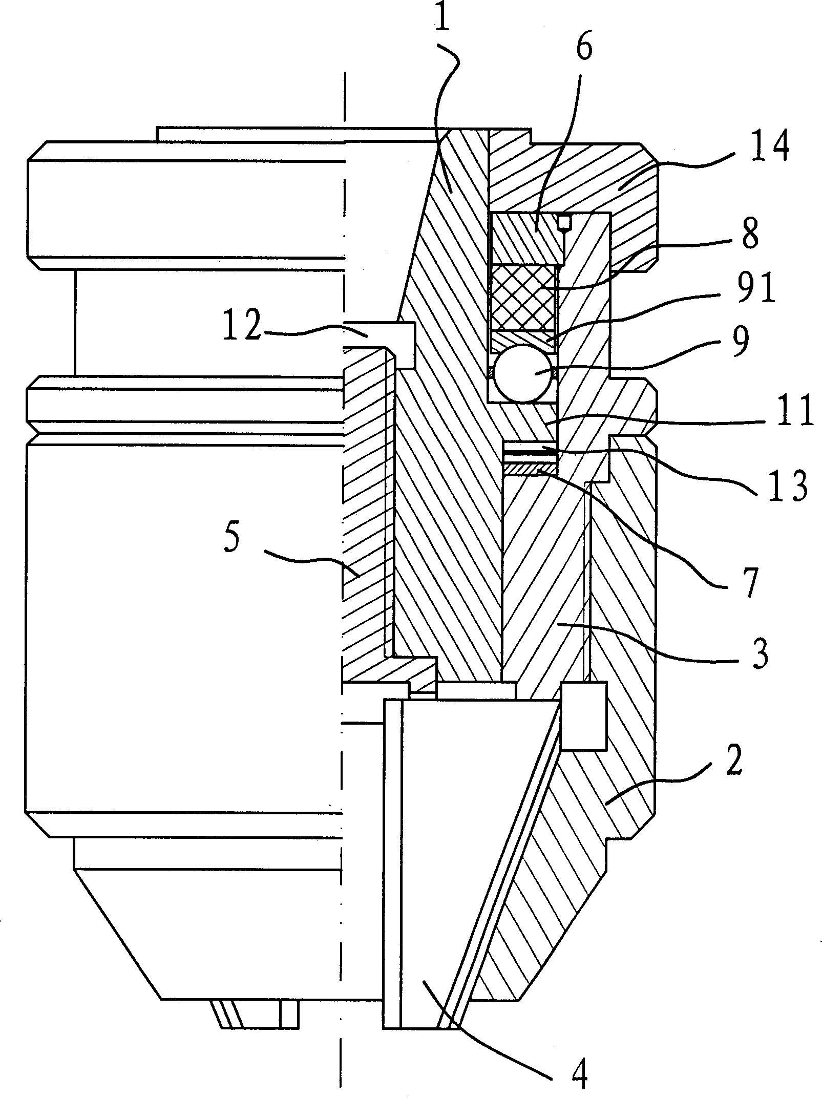
[0018] Such as figure 1 As shown, the self-tightening drill chuck includes the main body 1 of the drill chuck, the ball cover 6, the jaw seat 3, the self-tightening screw 5, the jaw 4 and the outer casing 2 and other parts. The main body 1 is an approximately cylindrical structure with a through hole 12 in the center, and the self-tightening screw 5 is connected with the main body 1 through threads. In the process of rotating the main body 1, if the self-tightening screw 5 does not rotate, it will stretch up and down along the main body 1.

[0019] The jaw seat 3 is sleeved on the outside of the main body 1 . A ball cover 6 is arranged on the top of the jaw seat 3 . The ball cover 6 is fixed on the inner side of the jaw seat 3 . The main body 1 is confined in the jaw seat 3 by the ball cover 6 . The overcoat 2 is connected with the jaw base 3 through threads.

[0020] Like common drill chucks, there are three guide grooves at the head of the jaw seat 3, and jaws 4 are hou...


PUM


Abstract

A self-clinching fixture with improved structure for drill bit is composed of a main body with a lateral shoulder, a rolling ball cover, the bearing and elastomer between said shoulder and cover, jaw holder, jaws installed in said jaw holder, external jacket, self-fastening screw liked to main body via spiral threads, an elastic plate under said shoulder and having several elastic pieces with boss, and a unidirectional ratchet on the lateral lower surface of said shoulder.

Description

technical field [0001] The invention belongs to the technical field of machinery, and in particular relates to a drill chuck used on a machine tool or a drilling machine. Background technique [0002] On bench drills, electric drills or machine tools used in machinery manufacturing, electronic appliances, textiles, medicine and other industries, it is often necessary to use drill chucks to hold drilling cutting tools or tools. There are usually two types of existing drill chucks: one is the wrench drill chuck, which requires auxiliary tools when clamping and loosening the drill bit, and the operation is troublesome; the other is the self-tightening drill chuck. Chuck. The self-tightening drill chuck is easy to clamp the drill bit through the principle of self-tightening. But often because the clamping force is too large, it is very difficult to loosen the drill bit. [0003] For this reason, many people are studying this problem, and have proposed v...

Claims


Application Information

Patent Timeline
Patent Type & Authority Patents(China)
IPC IPC(8): B23B31/12B23B51/12B23Q3/12
Inventor 游友民
Owner 游友民
Why Eureka
Try Eureka