Check patentability & draft patents in minutes with Patsnap Eureka AI!

Interrupt signal control method

A technology for interrupting signals and control methods, which is applied in measuring devices, measuring flow/mass flow, liquid/fluid solid measurement, etc., and can solve the problem of not being able to trigger and stop the clock control module normally, and not being able to wake up the computer system to restore the normal working mode, etc. question

Active Publication Date: 2006-07-26
VIA TECH INC
View PDF0 Cites 1 Cited by
  • Summary
  • Abstract
  • Description
  • Claims
  • Application Information

AI Technical Summary

Problems solved by technology

[0012] However, since the above two kinds of message signaled interrupts (MSI for short) both exist in the form of memory write cycles, and in the normal existing processing mode, the memory write cycles are for connection The system memory 70 on the north bridge chip 3 is connected to the north bridge and cannot be transmitted to the south bridge chip 2, so the stop clock control module (STPCLK control module) 20 cannot be triggered normally to remove (de-assert) the resulting stop Clock signal (STPCLK#)
Therefore, in this new generation system state, both the first peripheral device 4 and the second peripheral device 6 cannot effectively wake up the computer system from the power saving mode and return to the normal operating mode.

Method used


Image

  • Interrupt signal control method
  • Interrupt signal control method
  • Interrupt signal control method

Examples


Embodiment Construction

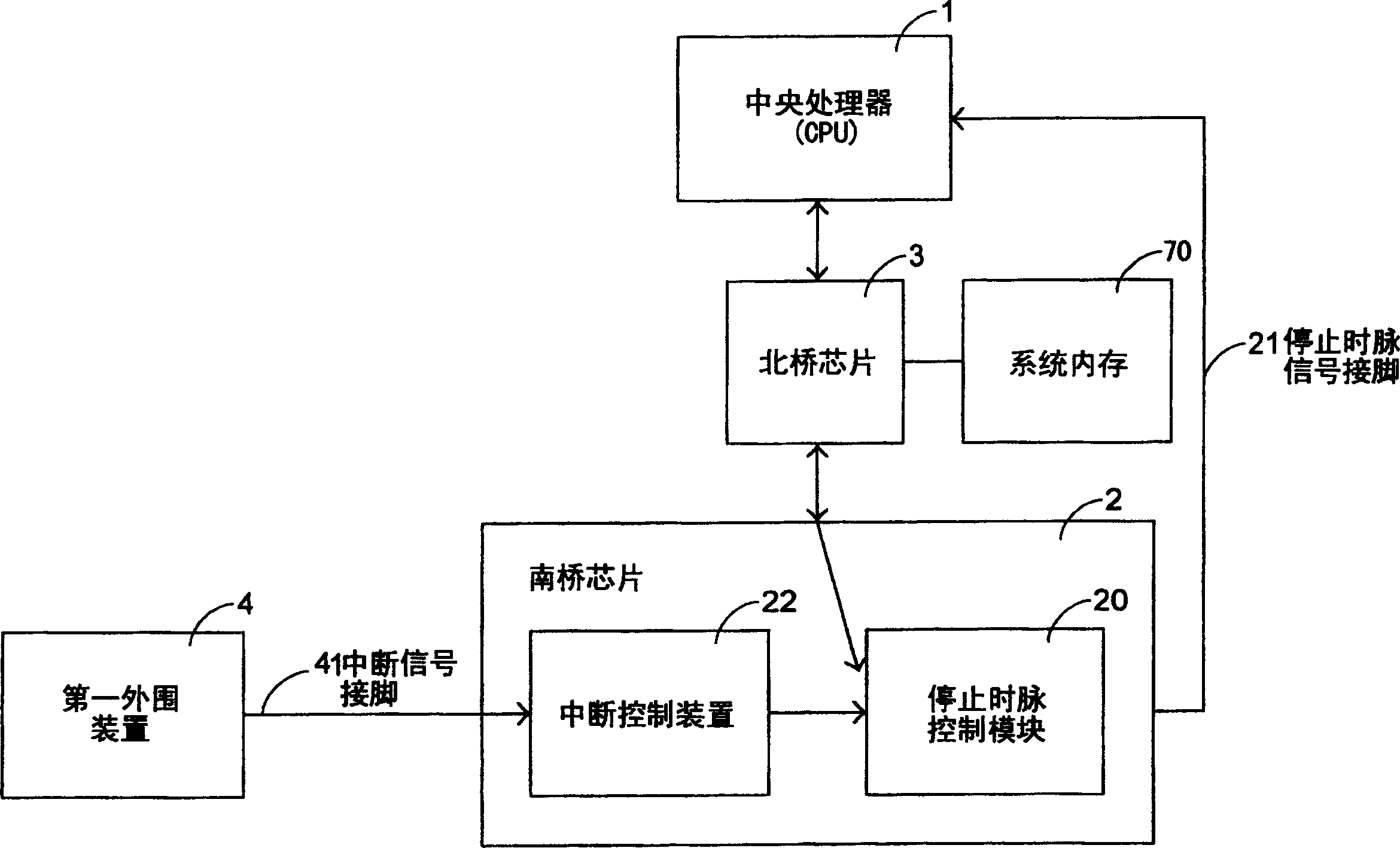
[0032] See image 3 , which is a functional block diagram of a preferred embodiment proposed by the present invention to improve the existing defects. The present invention is mainly an interrupt signal control system, which can be set in a computer system, and the computer system has Shown central processing unit 1, north bridge chip 3, system memory 70, south bridge chip 2, first peripheral device 4 and second peripheral device 6, and interrupt signal control system of the present invention mainly comprises a north bridge chip 3 The interrupt state indication pin 301 is connected with the stop clock control module (STPCLK control module) 20 integrated in the south bridge chip 2 .

[0033]In this way, when the central processing unit 1 is in the power-saving mode of C2 or C3, the first peripheral device 4 or the second peripheral device 6 passes through the peripheral component interface bus 40, the south bridge chip 2 or the peripheral component interface bus 60, the periphe...


PUM


Abstract

The invention discloses a kind of control method for interrupt signal, which is applied to the computer system. The computer system has centre processor, a south bridge chip, a north bridge chip, a bus bridge connecting device, a south bridge chip, the first outer device and the second outer device, the control method includes following steps: the first outer device connected to the south bridge chip electrically sends out the first interrupt signal to the north bridge chip; the second outer device connected to the bus bridge connecting device electrically sends out the second interrupt signal to the north bridge chip; the north chip decodes the received the interrupt signal, when confirming the signal is an interrupt signal, it generates an interrupt state instruction information; and interrupt information is transmitted to the south bridge chip through an interrupt state instruction path, thus the south bridge chip can release the electricity saving state of the centre processor.

Description

technical field [0001] The invention relates to an interrupt signal control method, especially the interrupt signal control method applied in a computer system. Background technique [0002] The power-saving mechanism is widely used in computer systems, and the power-saving modes applied to the central processing unit (CPU) are divided into quite a few levels and types (such as Advanced Configuration and Power Interface (Advanced Configuration and Power Interface, referred to as C1, C2, and C3 modes defined in the ACPI) specification), but its purpose is nothing more than to reduce energy consumption and provide a lower temperature stable circuit operating environment. And under the general framework (see figure 1 shown in the schematic diagram of the existing computer system architecture), the mechanism for the central processing unit (CPU) 1 of the computer system to recover from the power-saving mode to normal operation is implemented by the South Bridge chip (South Brid...

Claims


Application Information

Patent Timeline
Patent Type & Authority Patents(China)
IPC IPC(8): G06F1/26
Inventor 何宽瑞黄宗庆钟健平
Owner VIA TECH INC
Features
  • R&D
  • Intellectual Property
  • Life Sciences
  • Materials
  • Tech Scout
  • Unparalleled Data Quality
  • Higher Quality Content
  • 60% Fewer Hallucinations
Learn More