Control method of power converter in speed regulating system for three phase switched magnetic resistant motor

A reluctance motor and power converter technology, which is applied in the direction of a single motor speed/torque control, AC motor control, AC power input conversion to DC power output, etc. The effect of volume output, reduction of turns, and improved running performance

Inactive Publication Date: 2006-07-26
HEFEI UNIV OF TECH
View PDF0 Cites 3 Cited by
  • Summary
  • Abstract
  • Description
  • Claims
  • Application Information

AI Technical Summary

Problems solved by technology

[0010] 2. Considering that when V1V5 is switched to V2V6, the flow direction of the excitation current of the motor b-phase winding will be reversed. When other energized states are switched, the other two-phase windings also have this problem. In the actual circuit control, the motor winding must be considered The process of current commutation and current attenuation, that is, commutation and freewheeling problems
[0011] Through theoretical calculations and practical tests, the above two energization methods are directly applied to a three-phase switched reluctance motor speed control system with a three-phase inverter bridge as a power converter. There is a big gap in the application effect of the SR motor of the

Method used


Image

  • Control method of power converter in speed regulating system for three phase switched magnetic resistant motor
  • Control method of power converter in speed regulating system for three phase switched magnetic resistant motor
  • Control method of power converter in speed regulating system for three phase switched magnetic resistant motor

Examples


Embodiment Construction

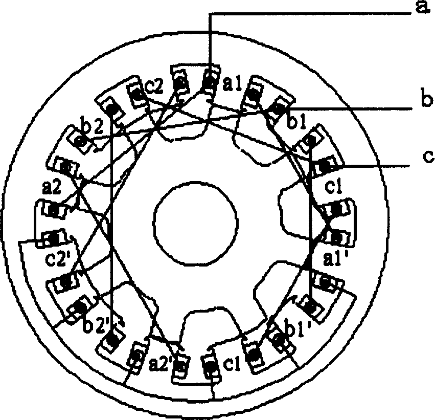
[0033] see image 3 , this embodiment uses a three-phase switched reluctance motor, and a three-phase inverter bridge power converter is set.

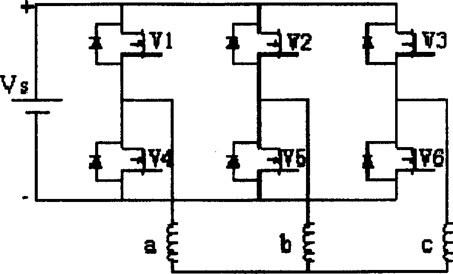
[0034] Such as figure 2 , image 3 As shown, the gear ratio of the stator and the rotor of the switched reluctance motor is 12 / 8, so every 45° mechanical angle of the motor is equal to 360° electrical angle. As shown in the figure, each phase winding of the motor has two branches, and the two windings of each branch are connected in reverse series, and each phase is connected end to end to form a three-phase star connection. For example, in phase A, a branch is formed by winding a1 and a1' in reverse series, and another branch is formed by winding a2 and a2' in reverse series. Phase B and phase C are also provided with the same structure.

[0035] image 3 As shown, the power converter adopts a three-phase inverter bridge power converter composed of six power tubes V1, V4, V2, V5, V3, and V6, and each power tube has its own anti-...


PUM


Abstract

In this controlling method six power tubes constructs the three phase inversion bridge power converter. It each power tube, the reversal parallel connected diode is installed. In the speed adjustment system, the three-phase switch magnetic resistance motor is applied as the executive component. The end of the three-phase coil of the motor is in three-phase star connection, the top of the three-phase coil is connected with the three bridge arms. By this effective control method, the problem of excess connecting wires is solved.

Description

Technical field: [0001] The invention relates to a control method of a power converter in a motor speed control system, more specifically a control method for a power converter in a switched reluctance motor speed control system. Background technique: [0002] Switched Reluctance Drive (SRD for short) is a new type of AC speed control system developed in the mid-1980s, which integrates Switched Reluctance Motor (SR Motor for short) with power electronics technology and control technology In one body, it has the advantages of asynchronous motor frequency conversion speed control system and DC motor speed control system. It is used in various fields such as traction transportation, general industry, aviation industry and household appliances, showing strong market competitiveness. [0003] Reluctance motors cannot be directly connected to the grid for steady-state operation like cage induction motors, but must be used together with a drive power supply. In terms of functional...

Claims


Application Information

Patent Timeline
Patent Type & Authority Patents(China)
IPC IPC(8): H02P6/08H02M7/5387H02P25/092H02P25/098
Inventor 黄海宏张敬华
Owner HEFEI UNIV OF TECH
Why Eureka
Try Eureka