
Plate permanetic linear synchronous machine for machine tool feeding system

A permanent magnet linear synchronization and feeding system technology, applied in the propulsion system, electromechanical device, shape/style/structure of winding conductors, etc. The effect of large thrust, improved thrust and fast heat dissipation

Inactive Publication Date: 2004-12-08
TSINGHUA UNIV
View PDF0 Cites 16 Cited by
  • Summary
  • Abstract
  • Description
  • Claims
  • Application Information

AI Technical Summary

Problems solved by technology

[0006] The purpose of the present invention is to overcome the shortcomings of existing linear motors such as large linear thrust fluctuations, low motor thrust density, and low response speed, and provide a new type of permanent magnet linear synchronous motor with a flat plate structure

Method used


Image

  • Plate permanetic linear synchronous machine for machine tool feeding system
  • Plate permanetic linear synchronous machine for machine tool feeding system
  • Plate permanetic linear synchronous machine for machine tool feeding system

Examples


Embodiment Construction

[0018] Flat permanent magnet linear synchronous motors can be used in the feed drive system of high-speed CNC machine tools and machining centers, and can also be used in the feed drive system of various special processing equipment (such as laser cutting, plasma cutting, EDM, etc.).

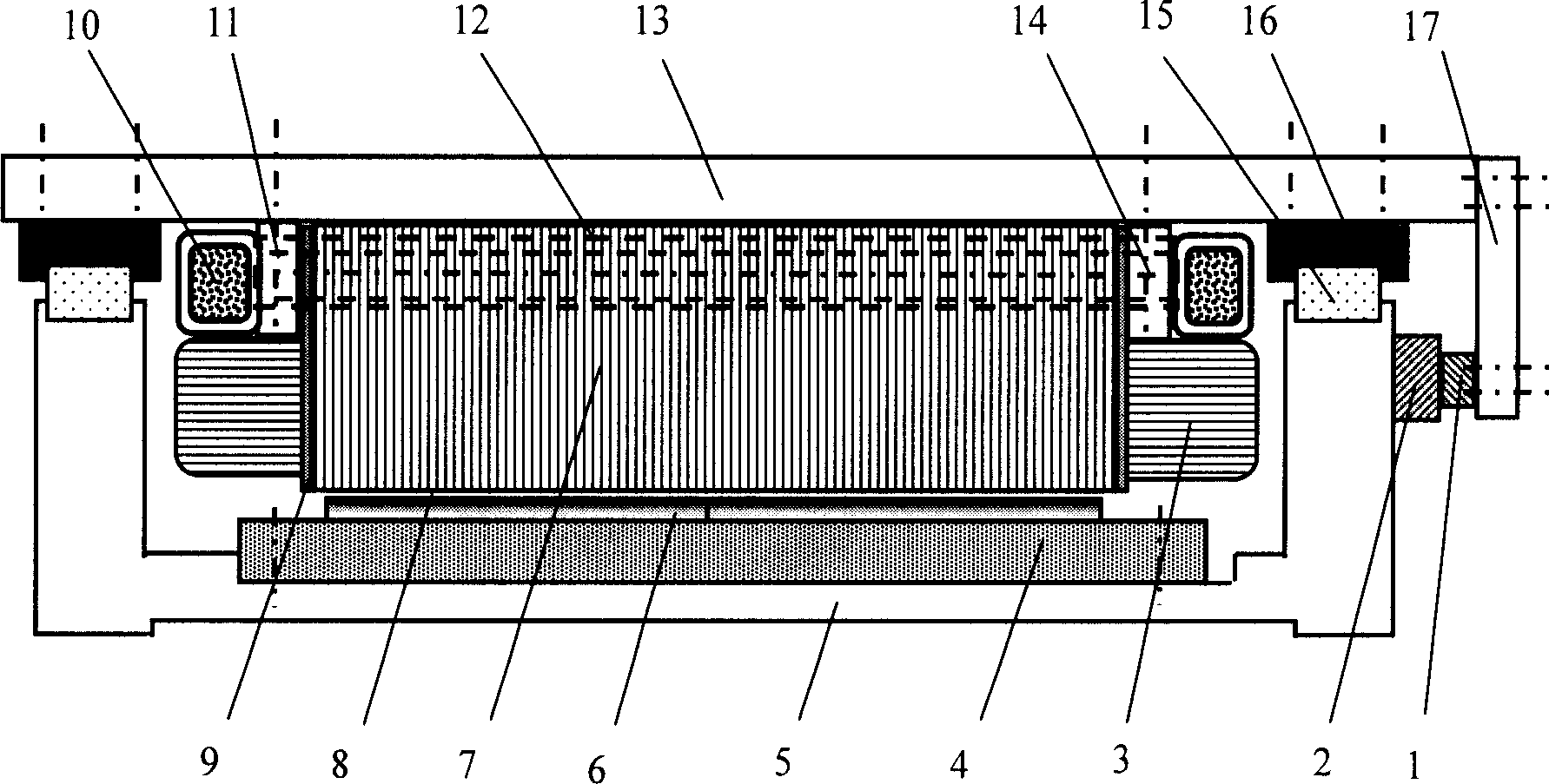
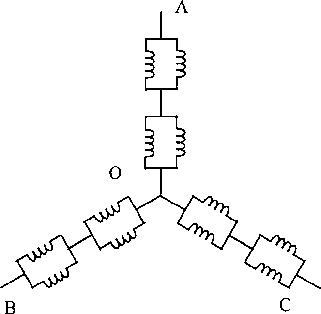
[0019] Such as figure 1 As shown, a flat permanent magnet linear synchronous motor includes a magnetic circuit structure and a mechanical structure. The magnetic circuit structure includes a primary composed of an iron core 7 and a winding 3, and a secondary composed of a magnetic steel 6 made of NdFeB permanent magnets and an electrical pure iron base plate 4 arranged on a base 5; the iron core 7 is to make with silicon steel laminations, with pressing plate 9, layering bar 11, compression screw rod 14 are compressed at two ends. The primary winding adopts a single-layer, full-pitch winding, and a star connection in series and parallel (see figure 2 ). The shape of the magnetic steel 6 can ...


PUM


Abstract

A flatbed permanent magnetism linear synchronization motor used in machine tool feed system belongs to device technology field for linear servo unit. For overcoming the disadvantage in current linear motor that is bigger fluctuation of linear thrust, lower density of motor thrust and lower response speed a permanent magnetism linear synchronization motor is provided, comprising magnetic circuit structure and mechanic structure, the above magnetic circuit structures the primary comprising iron core and winding and the secondary comprising magnetic steel and electric pure iron base board. The above mechanic structure comprises straight line supporting guide rail located between the primary and the secondary, cooling system, sensing and measuring system, dust-proof and safeguard structure. The above primary winding adopts single layer, full pitch winding and star-type connection combining with in series and parallel. The flatbed permanent magnetism linear synchronization motor has some advantages that are good stationarity, fast heat emission and big thrust. Its precision can reach submicro class.

Description

technical field [0001] The invention belongs to the equipment technical field of a linear servo unit, and can be directly used as a linear feed system of a high-speed metal cutting machine tool, and can also be used as a precision feed system of IC equipment and a special processing machine tool. Background technique [0002] High-speed machining is considered to be an advanced manufacturing technology in the 21st century. The speed of the electric spindle of the machine tool has reached more than 40,000r / min, so a high-speed feed system is required to match it. At the same time, in order to ensure the high precision of the workpiece and shorten the auxiliary processing time, the feed system must also have high acceleration (deceleration) speed, positioning accuracy and high rigidity. [0003] Traditionally, the method of "rotating motor + ball screw" is used to realize the feed drive of the machine tool. Its characteristics are: there are a series of intermediate links suc...

Claims


Application Information

Patent Timeline
Patent Type & Authority Applications(China)
IPC IPC(8): H02K1/17H02K3/04H02K41/03
Inventor 王先逵刘成颖赵彤石忠东陈定积吴丹刘泉李庆雷
Owner TSINGHUA UNIV
Learn More