Method for operating IC engine and control device thereof

A technology for control devices and internal combustion engines, which is applied in engine control, internal combustion piston engines, electrical control, etc., and can solve problems such as limiting conversion capabilities

Inactive Publication Date: 2006-08-16
ROBERT BOSCH GMBH
View PDF0 Cites 0 Cited by
  • Summary
  • Abstract
  • Description
  • Claims
  • Application Information

AI Technical Summary

Problems solved by technology

It is known that catalytic converters are subject to aging which limits their ability to convert

Method used


Image

  • Method for operating IC engine and control device thereof
  • Method for operating IC engine and control device thereof
  • Method for operating IC engine and control device thereof

Examples


Embodiment Construction

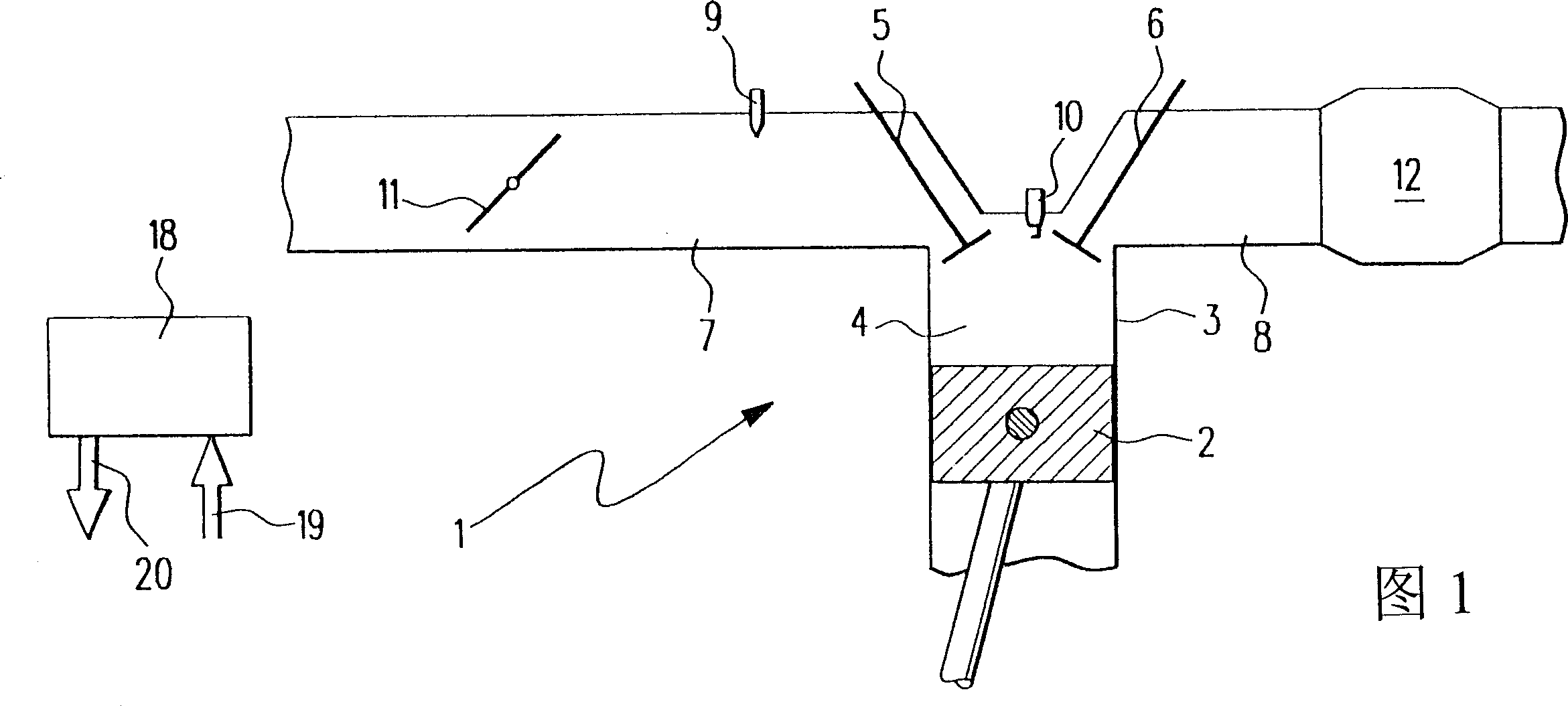
[0019] FIG. 1 shows a motor vehicle internal combustion engine 1 in which a piston 2 can reciprocate in a cylinder 3 . Cylinder 3 has a combustion chamber 4 which is bounded by piston 2 , intake valve 5 and exhaust valve 6 . An intake pipe 7 is connected to the intake valve 5 , and an exhaust pipe 8 is connected to the exhaust valve 6 .

[0020] There is a fuel injection valve 9 in the intake pipe 7 . A spark plug 10 projects into the combustion chamber 4 in the region of the intake valve 5 and the exhaust valve 6 . Fuel can be sprayed into intake pipe 7 li by fuel injection valve 9. The air / fuel mixture drawn into combustion chamber 4 can be ignited by means of spark plug 10 .

[0021] A rotatable throttle valve 11 is installed in the intake pipe 7 . The air quantity fed into the combustion chamber 4 depends on the angular position of the throttle valve 11 . A catalyst 12 for purifying exhaust gas produced by fuel combustion is installed in the exhaust pipe 8 .

[0022]...


PUM


Abstract

An internal combustion engine, especially for a motor vehicle, is described, which is provided with a catalytic converter which can be charged with hydrocarbons. The converting capability of the catalytic converter can be determined by a control apparatus. The converting capability of the catalytic converter is determined by the control apparatus by means of a combination of a passive and an active diagnostic method (27, 31).

Description

technical field [0001] The invention relates to a method for operating an internal combustion engine, in which method a catalytic converter can be loaded with hydrocarbons. The invention likewise relates to a control device for using such a method for operating an internal combustion engine. Background technique [0002] Such a method, such a control device and such an internal combustion engine are known, for example, from the so-called intake manifold injection. There, the fuel is injected into the intake manifold of the internal combustion engine during the intake phase. In addition, hydrocarbons formed when fuel is burned are converted into carbon dioxide in the catalytic converter. It is known that catalytic converters are subject to aging which limits their conversion capacity. [0003] The method mentioned at the outset is also known from direct injection internal combustion engines. There, the fuel is injected directly into the combustion chamber of the internal ...

Claims


Application Information

Patent Timeline
Patent Type & Authority Patents(China)
IPC IPC(8): F01N11/00F02D45/00F01N3/20F01N3/24
CPCF01N11/007Y02T10/47F01N2550/02F01N11/002F01N11/00Y02T10/40F02D41/14
Inventor 埃伯哈特·施奈贝尔埃里克·施奈德安德烈亚斯·克林安德烈亚斯·布卢门施托克
Owner ROBERT BOSCH GMBH
Why Eureka
Try Eureka