Multifunctional igbt drive circuit

A drive circuit, multi-functional technology, applied in the direction of output power conversion devices, electrical components, etc., can solve the problems of affecting the accuracy, reducing the reliability of IGBT modules, and affecting the equipment, so as to avoid the interference of external factors and improve the application Flexibility, the effect of reducing the cost of use

Active Publication Date: 2018-06-29
CHONGQING UNIV
View PDF4 Cites 0 Cited by
  • Summary
  • Abstract
  • Description
  • Claims
  • Application Information

AI Technical Summary

Problems solved by technology

[0002] IGBT modules are widely used in fields such as locomotive traction, electric vehicles, aviation power supplies, and renewable energy grid-connected power generation. In these fields, the application conditions are complex and the processing power fluctuates randomly, which makes the IGBT modules bear unbalanced electrothermal stress, which is easy to cause Aging of IGBT modules, thereby reducing the reliability of equipment using IGBT modules
[0003] Since the parasitic parameters of the IGBT module will change accordingly during the aging process, in order to detect the aging state of the IGBT module, the parasitic parameters of the IGBT module are generally detected to evaluate the aging state of the IGBT module. The existing method is Dismantling the IGBT module in a certain device from the device, disconnecting the IGBT module from the original drive circuit, and then testing it through special testing equipment, this method wastes huge manpower and material resources, and is inefficient, and more importantly Yes, during the disassembly process, the IGBT module will be affected due to the disassembly operation and other reasons, that is to say, the parameters in the final test may be generated by the joint action of disassembly operation and electrothermal stress, thus affecting the accuracy of the final test

Method used


Image

  • Multifunctional igbt drive circuit
  • Multifunctional igbt drive circuit
  • Multifunctional igbt drive circuit

Examples


Embodiment Construction

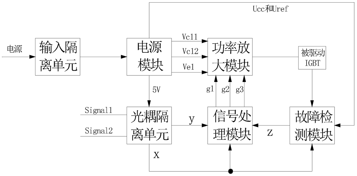
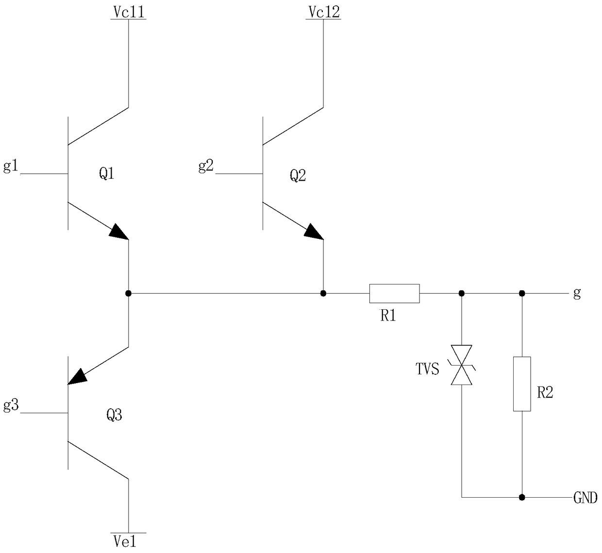
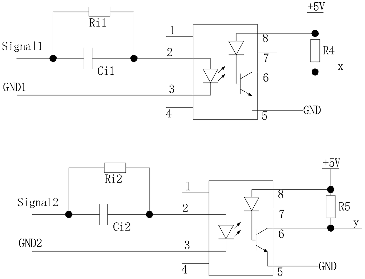
[0026] figure 1 It is a block diagram of the present invention, figure 2 It is the circuit schematic diagram of the power amplification module of the present invention, image 3 It is the circuit schematic diagram of the optocoupler isolation unit of the present invention, Figure 4 It is the circuit principle diagram of the fault detection unit of the present invention. As shown in the figure, a multifunctional IGBT drive circuit provided by the present invention includes a power supply module, a signal processing module and a power amplification module, and the power supply module contributes to the signal processing module and the power amplification module supply power, the signal processing module outputs a control signal to the power amplification module, and the power amplification module outputs an IGBT drive signal, an IGBT test signal or an IGBT shutdown signal according to the control signal output by the signal processing module, through this The structure can n...


PUM


Abstract

The invention provides a multifunctional IGBT driving circuit. The multifunctional IGBT driving circuit comprises a power supply module, a signal processing module and a power amplifying module, wherein the power supply module supplies power to the signal processing module and the power amplifying module; the signal processing module outputs a control signal to the power amplifying module; and the power amplifying module outputs an IGBT driving signal, an IGBT test signal or an IGBT switch-off signal according to the control signal output by the signal processing module. By adoption of the structure, the driving circuit can drive the IGBT to use normally as well as can perform parameter test without detaching the IGBT; therefore, the online monitoring for the parasitic parameters of the IGBT module is realized; manpower and material resources are saved, the test efficiency is improved, the use cost is lowered, and the application flexibility is improved; and in addition, interferences from the external factors can be effectively avoided to ensure the test accuracy so as to accurately evaluate the aging state of the IGBT module.

Description

technical field [0001] The invention relates to a driving circuit, in particular to an IGBT driving circuit with multiple functions. Background technique [0002] IGBT modules are widely used in fields such as locomotive traction, electric vehicles, aviation power supplies, and renewable energy grid-connected power generation. In these fields, the application conditions are complex and the processing power fluctuates randomly, which makes the IGBT modules bear unbalanced electrothermal stress, which is easy to cause The aging of the IGBT module reduces the reliability of the equipment using the IGBT module. [0003] Since the parasitic parameters of the IGBT module will change accordingly during the aging process, in order to detect the aging state of the IGBT module, the parasitic parameters of the IGBT module are generally detected to evaluate the aging state of the IGBT module. The existing method is Dismantling the IGBT module in a certain device from the device, discon...

Claims


Application Information

Patent Timeline
Patent Type & Authority Patents(China)
IPC IPC(8): H02M1/08
CPCH02M1/08
Inventor 孙鹏菊龚灿杜雄周雒维
Owner CHONGQING UNIV
Why Eureka
Try Eureka