Fuel jetting valves

A technology for fuel injection valves and fuel passages, which is applied to fuel injection devices, charging systems, engine components, etc., and can solve the problems of fuel particle sacrifice, difficulty in spraying orifice plates, and rising production costs

Inactive Publication Date: 2006-08-30
MITSUBISHI ELECTRIC CORP
View PDF1 Cites 0 Cited by
  • Summary
  • Abstract
  • Description
  • Claims
  • Application Information

AI Technical Summary

Problems solved by technology

[0004] However, in the case of forming the above-mentioned tapered injection holes on the injection orifice plate, very troublesome steps are required for its manufacture and size control, which leads to problems in that the productivity of the fuel injection valve decreases and the production cost increases.
In addition, generally speaking, the thinner the thickness of the orifice plate, the better the atomization of the fuel. However, once the thickness of the orifice plate is reduced, the spray angle of the fuel injected from the injection hole increases. Due to the directionality of the fuel spray and the strength of the plate, it is difficult to make the orifice plate with a thickness of less than 0.1mm to some extent, so the atomization of the fuel has to be sacrificed

Method used


Image

  • Fuel jetting valves
  • Fuel jetting valves
  • Fuel jetting valves

Examples


no. 1 Embodiment

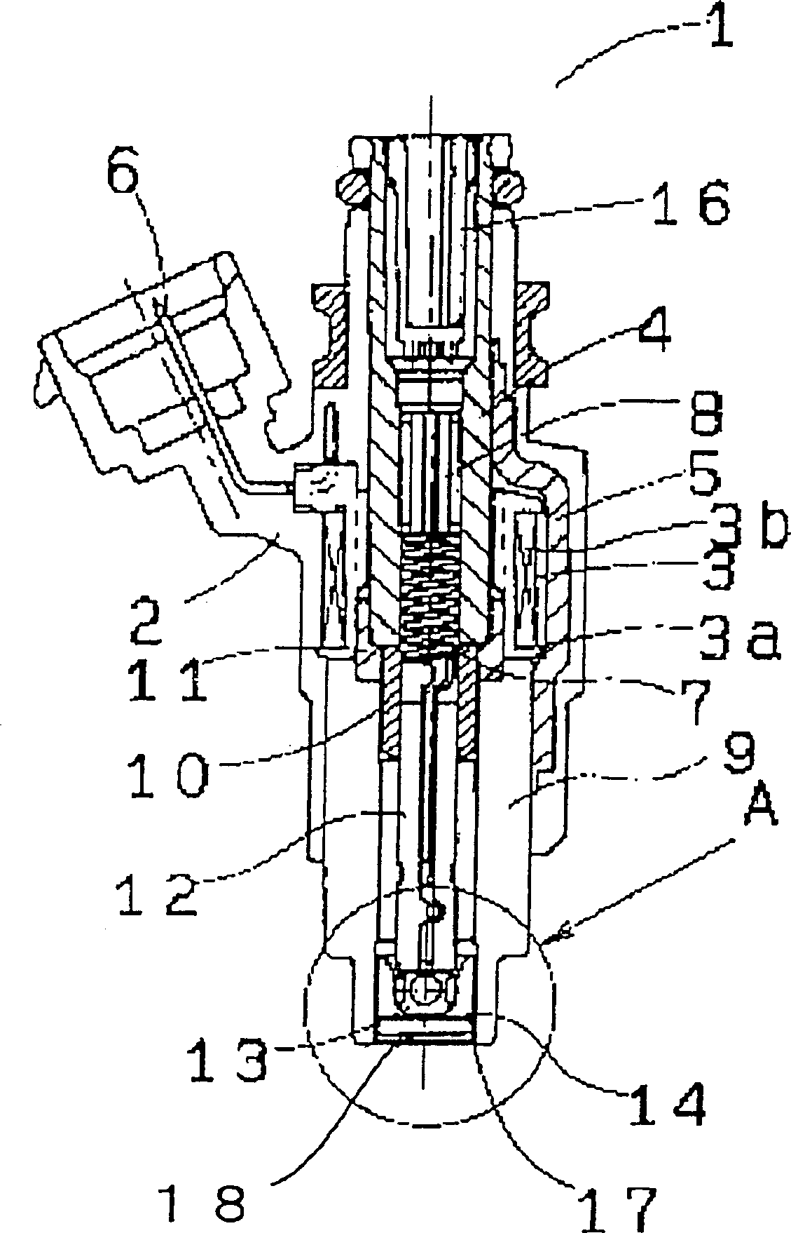
[0021] The first embodiment of the present invention will be described below. figure 1 The first embodiment of the present invention is a side cross-sectional view showing the overall structure of the fuel injection valve 1 . The fuel injection valve 1 is integrally formed with an electromagnetic coil 3 , a fixed iron core 4 , and a metal plate 5 constituting a magnetic channel arranged inside a resin housing 2 . The electromagnetic coil 3 is composed of a resin-made bobbin 3 a, a coil 3 b wound on the outside thereof, and a terminal 6 provided for connection to the outside, and is integrally molded with the resin-made casing 2 .

[0022] An adjuster 8 for adjusting the compression spring 7 is fixed inside the fixed iron core 4 . One end of the two metal plates 5 constituting the magnetic channel is fixed on the fixed iron core 4 by welding, and the other end is welded on the electromagnetic tube 9 constituting the magnetic channel. A movable iron core 10 provided inside th...

no. 2 Embodiment

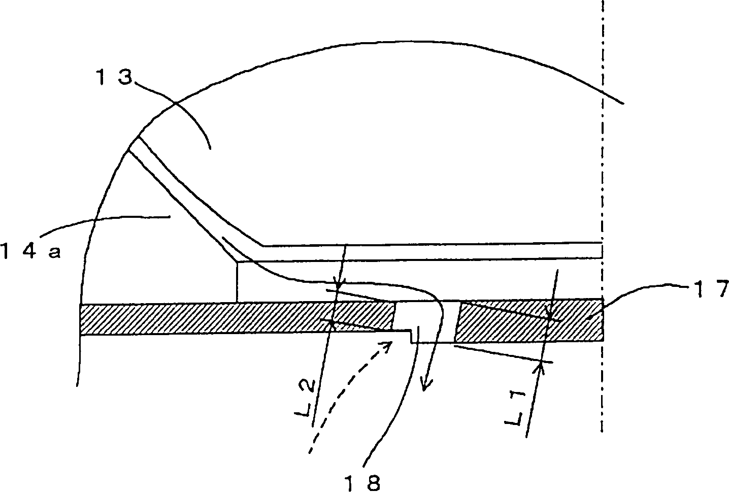
[0030] In the above-described first embodiment, the thickness of the inner peripheral side of the orifice plate 17 is larger than the thickness of the outer peripheral portion, and the injection holes are formed across the stepped portion where the thickness of the nozzle changes, but the fuel pressure is large, and it is necessary to ensure the injection orifice plate. In the case of strength of 17, it is also possible to constitute Figure 5 Orifice plate 17 shown.

[0031] like Figure 5 As shown, the injection hole plate 17 is formed with an annular groove 19b centered on the axis of the fuel injection valve, and the injection hole 18 is formed with a radially inner surface spanning the groove 19b. By providing the injection hole 18 in this way, a part of the outer side in the radial direction of the injection hole 18 is in a notch state, and a relationship of L1>L2 can be established.

[0032] Such an orifice plate is the same as the orifice plate of the above-described...

no. 3 Embodiment

[0035] In the above-mentioned first and second embodiments, one stepped portion or one groove is provided for the plurality of injection holes. Image 6 As shown, one concave portion 19c is provided for one injection hole 18, each injection hole 18 is formed across the radially inner surface of the concave portion 19c, and a part of the radially outer side of the injection hole 18 is in a notch state, so that L1> L2 relationship.

[0036]Like the orifice plate of the above-described first embodiment, such an orifice plate can be manufactured with simple steps, such as the step of forming the concave portion by punching or the like and the step of forming the orifice by punching or the like, without sacrificing the orifice. The strength of the plate and the directionality of the fuel injection make it possible to obtain an electromagnetic fuel injection valve that atomizes the fuel spray. Further, only the portion where the plate thickness is reduced is in the groove 19b, and ...


PUM


Abstract

A fuel injection valve includes a valve seat portion, a nozzle hole plate, and a valve member. The valve seat portion has an inner circumferential surface including a valve seat. The nozzle hole plate is disposed at a downstream side of a fuel passage of the valve seat. The nozzle hole plate has a nozzle hole for injecting fuel flowing out from the fuel passage. The valve member seats on the valve seat to close the fuel passage and unseats from the valve seat to open the fuel passage. Diameter of the inner circumferential surface decreases as approaching to a downstream side. The nozzle hole of the nozzle hole plate is formed so that length of radial outside of the nozzle hole with respect to a shaft center of the fuel injection valve is smaller than that of radial inside of the nozzle hole.

Description

technical field [0001] The present invention relates to a fuel injection valve for injecting fuel to an internal combustion engine, in particular to its orifice plate. Background technique [0002] Conventionally, a fuel injection valve that injects fuel from each injection hole is known by providing an injection hole plate with a thin plate formed with a plurality of divided holes on the downstream side of the fuel of the valve portion forming the valve member and the valve seat. In this type of fuel injection valve, the injection holes are generally the same diameter from the injection hole inlet to the injection hole outlet. Once the fuel flows into the injection holes of the same diameter, the fuel is not diffused along the inner peripheral surface of the injection hole in a liquid column shape. injection. The fuel that becomes such a liquid column is difficult to atomize, resulting in poor combustion of the internal combustion engine. [0003] In view of this situatio...

Claims


Application Information

Patent Timeline
Patent Type & Authority Patents(China)
IPC IPC(8): F02M61/18F02M51/06
CPCF02M61/1806F02M51/0678F02M61/1853F02M61/18
Inventor 宗实毅住田守
Owner MITSUBISHI ELECTRIC CORP
Why Eureka
Try Eureka