Cathode ray tube with reduced depth

A cathode ray tube, deep technology, applied in the field of deflection yoke

Inactive Publication Date: 2007-10-17
LG・菲利浦显示器公司
View PDF3 Cites 0 Cited by
  • Summary
  • Abstract
  • Description
  • Claims
  • Application Information

AI Technical Summary

Problems solved by technology

One disadvantage of CRTs compared to other types of display devices is the depth of the CRT.

Method used


Image

  • Cathode ray tube with reduced depth
  • Cathode ray tube with reduced depth
  • Cathode ray tube with reduced depth

Examples


Embodiment Construction

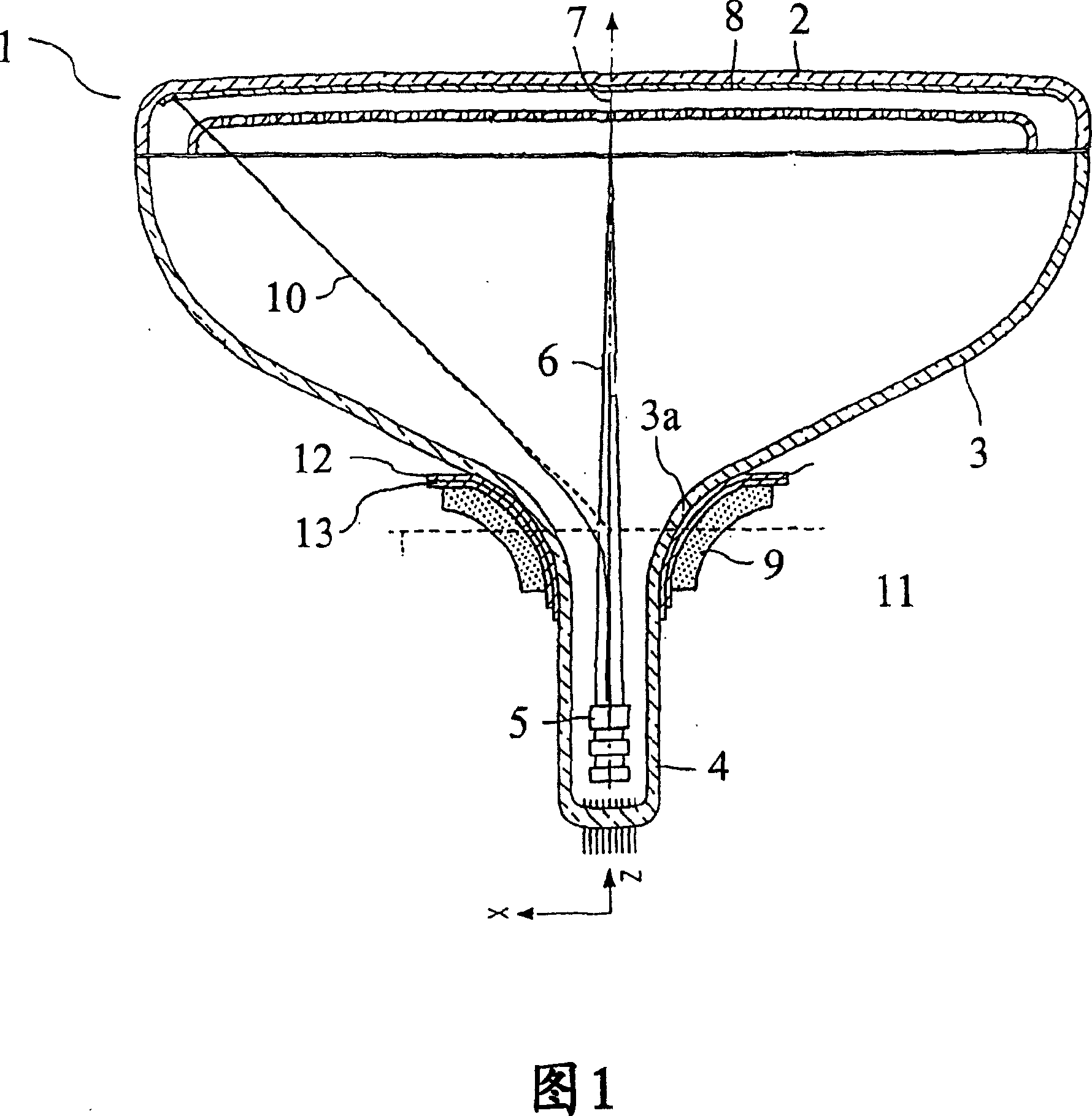
[0025] Fig. 1 shows a cathode ray tube and an image display apparatus according to a preferred embodiment of the present invention.

[0026] It comprises a cathode ray tube 1 comprising a faceplate part, sometimes called a display window 2, a funnel part 3 and a neck 4 (or neck as hereinafter referred to). In the neck 4, there is a device 5 for generating, in this example three in-line electron beams 6, for generating electron beams, wherein the axial planes are parallel to the long axis of the display screen, such devices are hereafter Abbreviated to the word "electron gun". The means used to generate the electron beam is usually an axial electron gun. This design is the standard design. The inner surface of the panel part 2 comprises a plurality of fluorescent elements forming a display screen 8 . When one or more electron beams 6 hit the fluorescent element, the fluorescent element fluoresces, thereby creating a visible point on the display screen 8 . In the undeflected...


PUM


Abstract

A cathode ray tube (1) comprises a panel portion (2), a funnel portion (3) and a neck portion (4) with an electron gun (5). The screen of the cathode ray tube has a diagonal D of more than 28 inches. The panel portion (2) has a seal edge (21a) with a thickness (Tshort) at the end of the short axis of 0.019D to 0.0275D, where D is the length of the diagonal of the screen, and a front part (22) having a thickness (Tfront ) at least 10% smaller than the thickness (Tshort ) of the edge of the panel portion. The depth of the cathode ray tube at a point halfway between the centre of the screen and the end of the diagonal is less than 0.3D (HD / 4<0.3D).

Description

technical field [0001] The present invention relates to a cathode ray tube comprising a panel portion having a major axis, a minor axis and a diagonal, a funnel portion and a neck, comprising an electron gun for generating one or more electron beams, and mounted on said A deflection yoke on the funnel portion is used to generate an electromagnetic field for deflecting the electron beam. [0002] The invention also relates to a panel section for a cathode ray tube. [0003] The invention also relates to a display device comprising a CRT. Background technique [0004] Such cathode ray tubes (CRTs) are known. Several types of cathode ray tubes exist, the most familiar of which are those with a shadow mask. Other types of cathode ray tubes are, for example, pilot tubes and tubes in which a stretched mask is used. [0005] A cathode ray tube as a type of display device must compete with various other types of display devices such as LCD's PDP and the like. These various type...

Claims


Application Information

Patent Timeline
Patent Type & Authority Patents(China)
IPC IPC(8): H01J29/86
CPCH01J2229/862H01J29/861
Inventor 保罗·斯特肯莫翰姆德·卡里尔
Owner LG・菲利浦显示器公司
Why Eureka
Try Eureka