Heater for forming base plate with thermal resistance and image heating apparatus using the same heater
A technology for heating devices and heaters, which is applied in the direction of electric heating devices, ohmic resistance heating, roller heating devices, etc., and can solve the problems of uncontrollable heater costs and expensive palladium
- Summary
- Abstract
- Description
- Claims
- Application Information
AI Technical Summary
Problems solved by technology
Method used
Image

Examples
no. 1 Embodiment
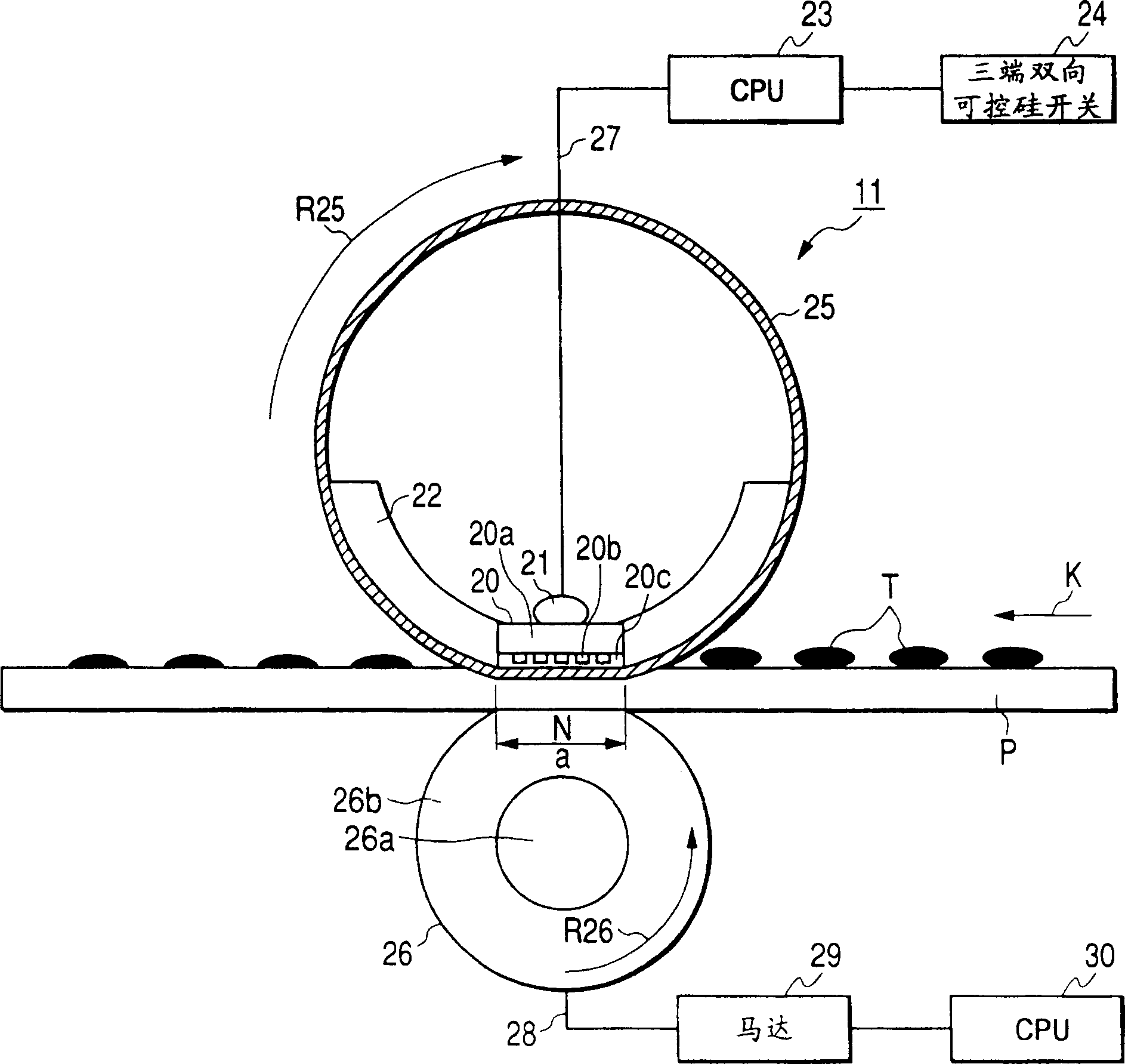
[0035] The heating device in this embodiment is an image heating device of a pressure roller driving method and a film heating method using a fixing film (hereinafter also referred to as a fixing belt or a flexible roller) as a heating element.
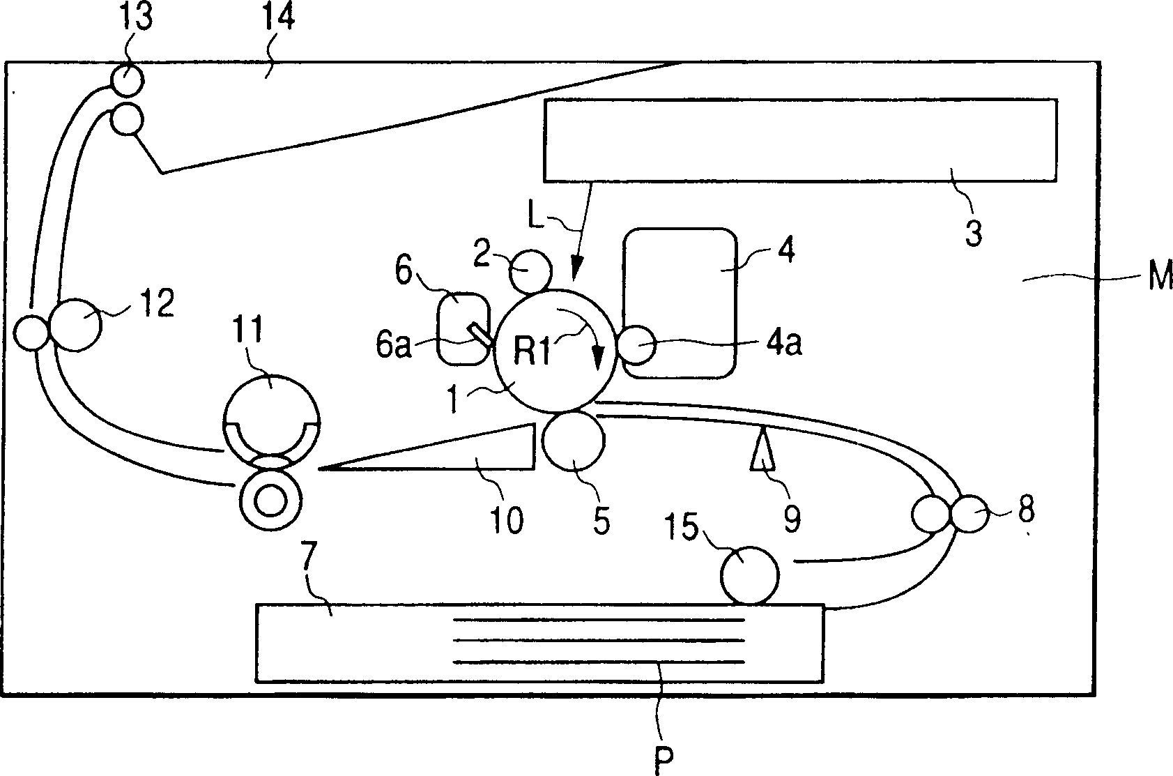
[0036] figure 1 It is a vertical cross-sectional view showing a schematic configuration of a laser printer (hereinafter referred to as an image forming device) equipped with the image heating device of the present invention.
[0037] 1) Brief structure of the imaging device as a whole
[0038]This laser beam printer includes a drum-shaped electrophotographic photoreceptor (hereinafter referred to as a “photosensitive drum”) 1 as an image carrier. The photosensitive drum 1 is rotatably supported by the apparatus main body M, and is driven to rotate in the direction of the arrow R1 at a predetermined processing speed by a driving device (not shown).
[0039] Around the photosensitive drum 1, a charging roller (charging device) 2, an ...
no. 2 Embodiment
[0070] In the above-mentioned first embodiment, the heating value is the same at the upstream and downstream of the heater substrate 20a in the recording material conveyance direction, but in this embodiment, as Figure 7A and Figure 7B As shown, by changing the resistance value of the heating resistor, the heating value of the upstream and downstream is changed, and the heating distribution of the heating resistor is optimized.
[0071] exist Figure 7A , connect all the heating resistors in series, assuming that from the upstream side, the resistance values of each heating resistor are R1, R2, R3, R4, R5, R6, in Figure 7B Among them, they are R1, R2, R3, and R4, and the resistance value becomes smaller from the upstream side to the downstream side (the heating resistor becomes thicker as it goes downstream). That is, whether in Figure 7A still in Figure 7B Among them, all are (resistance value of upstream) > (resistance value of downstream). For example, in Figu...
no. 3 Embodiment
[0085] like Figure 11A or Figure 11B As shown, the feature of this embodiment is: use one to form the forward path (upstream) heating resistor (the heating resistor connected to the power supply electrode 20d is one), and only the return path (downstream) heating resistor The heat generating resistors are spaced apart in the longitudinal direction (a plurality of heat generating resistors are connected in parallel to the power supply electrode 20e). One of its purposes is to prevent damage to the heater at a specific location and leakage of electricity even when the temperature detection element for safety measures does not work, thereby preventing malfunction of the computer communicating with it or electric shock to the user due to the leakage. In such a runaway state, the thermal stress on the substrate deforms the substrate so as to protrude toward the upstream side, thereby cutting off the upstream heating resistor and stopping the energization.
[0086] However, if t...
PUM
 Abstract
Description
Claims
Application Information
 - R&D
- Intellectual Property
- Life Sciences
- Materials
- Tech Scout
- Unparalleled Data Quality
- Higher Quality Content
- 60% Fewer Hallucinations
Browse by: Latest US Patents, China's latest patents, Technical Efficacy Thesaurus, Application Domain, Technology Topic, Popular Technical Reports.
© 2025 PatSnap. All rights reserved.Legal|Privacy policy|Modern Slavery Act Transparency Statement|Sitemap|About US| Contact US: help@patsnap.com