Automatic bicycle

A technology for automatic two-wheeled vehicles and pipes, applied to bicycles, motor vehicles, bicycle racks, etc., can solve the problems of reduced riding comfort, achieve the effects of improving riding comfort, increasing productivity, and reducing costs

Inactive Publication Date: 2006-09-06
HONDA MOTOR CO LTD
1 Cites 0 Cited by

AI-Extracted Technical Summary

Problems solved by technology

Furthermore, in the main pipe, in order to close the opening formed by cutting, the components of the body frame are welded, so the rigidity of the rear half of ...

Method used

By movable die 139 moving toward setting direction, the width on the first direction A1 of pipe material 120, that is, the outer diameter on the first direction A1 of pipe material 120 increases while, the first pipe wall uses the inner side of opening 150a The width in the first direction A1 between the first end surface 147a of the movable core 147 and the second end surface 144b of the fixed core 144 inside the second pipe wall opening 150b, that is, the width of the pipe material 120 in the first direction A1 The inner diameter is reduced, so by increasing the outer diameter of the pipe material 120 and reducing the inner diameter, the increase ratio of the wall thickness of the first and second pipe wall parts 121a, 121b corresponding to the increase of the outer diameter of the pipe material 120 can be increased, The enlargement of the pipe material 120 in the first direction A1 is suppressed, and the pipe material 120 having high local rigidity can be obtained. In addition, since the extrusion end 120b of the pipe 120 has a wall thickness of the predetermined width t4 and the inner diameter becomes larger, it is the same as the pipe whose outer diameter in the first direction A1 is reduced as it goes toward the extrusion end and the wall thickness is the predetermined width. Compared with the t4 pipe, the rigidity becomes higher.
In the extrusion molding device 130, while the blank 131 is extruded from the opening 150, the movable die 139 moves in a set direction, and the pipe material 120 defined by the first wall surface 143a and the second wall surface 148b The width in the first direction A1 increases, and at the same time, the widths of the first pipe wall opening 150a and the second pipe wall opening 150b in the first direction A1 increase, so on the one hand, the width in the first direction A1 In the part that increases along the length direction, the wall thicknesses of the first and second pipe wall parts 121a and 121b facing each other in the first direction A1 also increase. The predetermined width of the pipe material 120 in the second direction A2 is constant. As a result, the width in the first direction A1 is increased in the front portion in the longitudinal direction, and the wall thicknesses of the first and second pipe wall portions 121a, 121b facing each other in the first direction A1 are increased, so the rigidity is high, and only when it is necessary to While the rigid part has high rigidity, the width in the second direction A2 is kept constant, so that the pipe 120 can be compacted and formed easily by extrusion molding.
In the extrusion molding device 30, because the blan...

Abstract

The objective is to reduce the cost of a motorcycle, and to improve its ride quality by using an extruded head pipe having different rigidity in the longitudinal direction. This motorcycle is provided with a main pipe formed of a tubular member 20 and having a front end forming a connection part to the head pipe. The tubular member 20 is formed by integrally extruding a tubular wall 21 with connection walls 22 and 23 to connect tubular wall parts 21c and 21d facing each other in an inner space. A front part including the connection part of the main pipe is formed of a tubular part 24 having the connection walls 22 and 23, and at least a part of the rear part of the main pipe is formed of a tubular part 25 having no connection wall.

Application Domain

Extrusion diesExtrusion mandrels +2

Technology Topic

EngineeringRide quality +1

Image

  • Automatic bicycle
  • Automatic bicycle
  • Automatic bicycle

Examples

  • Experimental program(1)

Example Embodiment

[0037] Below, refer to Figure 1- Figure 25 Examples of the present invention will be described.
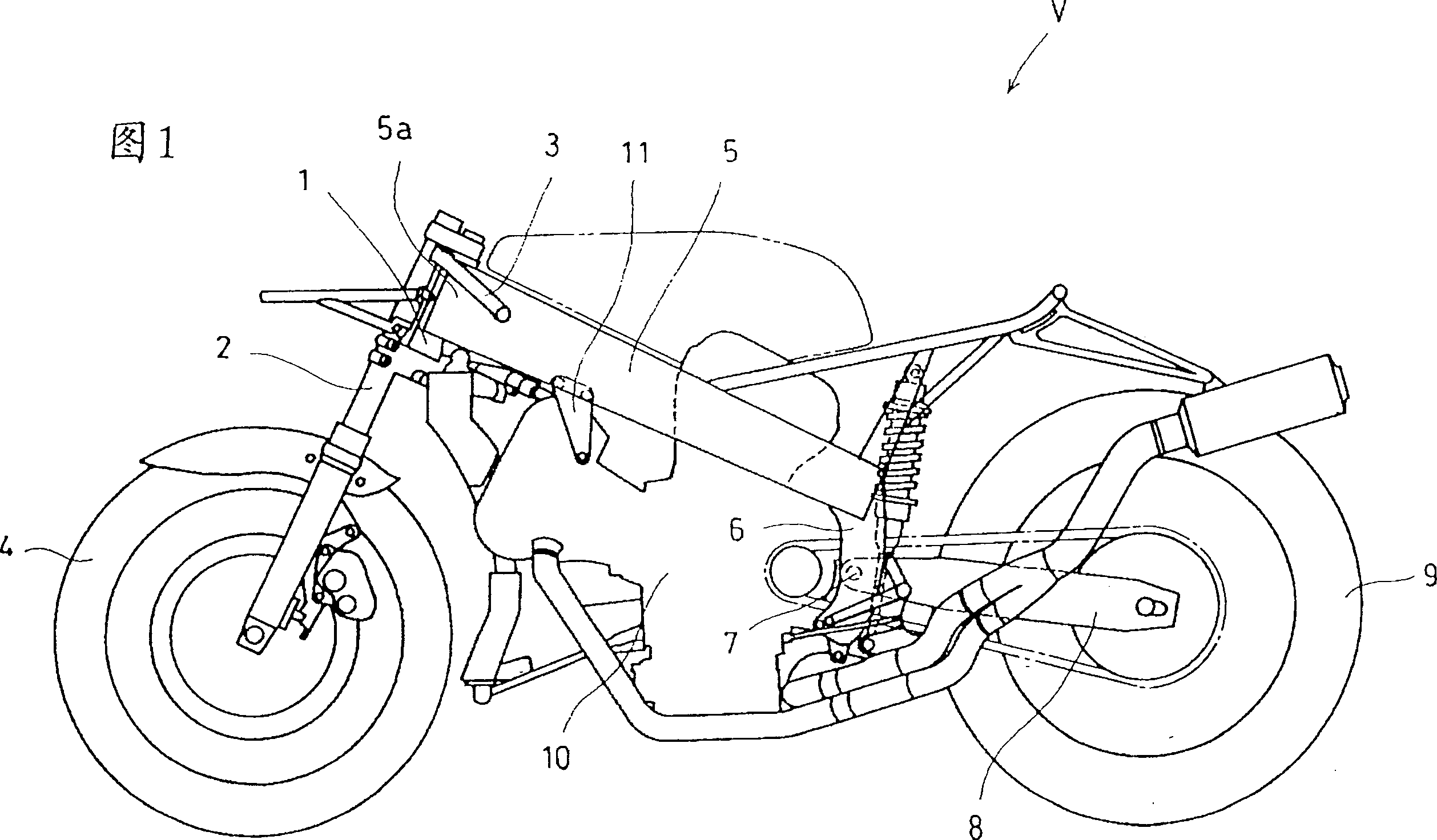
[0038] 1 to 10 show a first embodiment of the present invention, and Fig. 1 is a schematic left side view of a motorcycle V according to the present invention. In the motorcycle V, a handle 3 is provided at the upper end of a front fork 2 rotatably supported by a head pipe 1 , and a front wheel 4 is pivotally supported at the lower end thereof. A pair of left and right main pipes 5 whose front ends are connected to the head pipe 1 extend left and right while extending diagonally downward from the rear of the vehicle body in a bilaterally symmetrical manner, and are connected near the rear end by a cross pipe (not shown). . A pair of left and right pivot plates 6 are respectively connected to the rear ends of the two main pipes 5, and on the pivot 7 supported by the two pivot plates 6, the rear fork pivoting the rear wheel 9 is supported freely swinging up and down. 8. The front part of the internal combustion engine 10 is supported by a pair of left and right engine brackets 11 , and its rear part is supported on two main pipes 5 by two pivot plates 6 .
[0039] In addition, in the following embodiments, "up and down, front and rear, left and right" means "up and down, front and rear, left and right" based on the vehicle.
[0040] Each main pipe 5 is made of aluminum or aluminum alloy, such as figure 2 The illustrated pipe material 20 formed by extrusion molding is formed by subjecting it to processing such as bending. The pipe material 20 whose cross-sectional shape changes along the longitudinal direction has a first pipe wall portion (upper pipe wall portion) 21a and a second pipe wall portion (lower pipe wall portion) 21b facing each other in the vertical direction, and a pipe wall portion (lower pipe wall portion) 21b facing each other in the left-right direction. The pipe wall 21 formed by the third pipe wall portion (first side pipe wall portion) 21c and the fourth pipe wall portion (second side pipe wall portion) 21d has a constant wall thickness along the longitudinal direction, It has a substantially rectangular closed cross section that is long in the vertical direction.
[0041] Since loads in the vertical direction from the front fork 2 and the pivot shaft 7 act on the respective main pipes 5, the aforementioned loads and bending moments and torques based on the loads act on the respective main pipes 5 having the connecting portion 5a with the head pipe 1. Therefore, the front part of the main pipe 5 including the connection part 5a is a part requiring high rigidity. Therefore, in the inner space of the pipe material 20, the two connection walls 22, 23 connecting the third pipe wall portion 21c and the fourth pipe wall portion 21d serve as reinforcing walls, and are formed on the first pipe wall portion 21a and the second pipe wall portion 21b. Formed at intervals in the up and down direction.
[0042] The front part of the pipe material 20 constituting the front part of each main pipe 5 is a pipe material 24 having two connecting walls 22, 23. local space. In addition, the rear part of the pipe material 20 constituting the rear part of each main pipe 5 is the pipe material part 25 without the connecting walls 22 and 23, and a single inner space is formed by the pipe wall 21 of the pipe material 20 at this position.
[0043] Next, refer to image 3 ~ FIG. 9, the extrusion molding mechanism of the pipe material 20 is demonstrated. First, refer to image 3, the extrusion molding device 30 is provided with: accommodate the container 32 of aluminum or aluminum alloy as the billet 31 (billet) of the pipe 20, the die 33 for extrusion molding of the pipe, the extrusion block that the billet 31 is extruded from the container 32 34, and a rod 35 that transmits the force of the ram to the extrusion block 34. And pipe extruding mold 33 is provided with: relatively container 32 is fixed fixed male mold 36, overlaps on fixed male mold 36 and is fixed fixed female mold 37, and overlaps on fixed female mold 37 and can be moved along A movable die 39 whose overlapping surfaces can slide freely, and the dies 36 , 37 , 39 are sequentially arranged in the extrusion direction A0 of the billet 31 . Moreover, the fixed male mold 36 and the fixed female mold 37 that are integrated with each other constitute the fixed mold 38, and the driving device 40 drives the movable mold 39 in a direction intersecting with the extrusion direction A0, which is a vertical direction in the first embodiment. In the set direction, it moves relative to the fixed mold 38 along the aforementioned overlapping surface. Furthermore, a plurality of passages 41 are provided in the fixed male mold 36 for guiding the blank 31 to an opening 50 which will be described later.
[0044] With reference to Fig. 4~Fig. 9, as shown in Fig. 9 (A), the direction of the projection of the above-mentioned set direction to the vertical plane perpendicular to the extrusion direction A0 is the first direction A1 (in the first embodiment, the set direction It is the direction perpendicular to the extrusion direction A0, so the first direction A1 is consistent with the set direction.), in the fixed female mold 37, it is formed to have a long side parallel to the first direction A0 and a substantially rectangular cross section. The through hole 42, the wall surface 43 of the through hole 42 is parallel to the extrusion direction A0. 4, in the through hole 42, the support parts 36a, 36b are integrally provided on the fixed male mold 36, and are composed of a first sub-core 44a and a second sub-core 44b arranged in parallel with the first direction A1. The fixed core 44 is disposed so as to form a gap with the wall surface 43 . The wall surface 43 has: a first wall surface 43a and a second wall surface 43b that form parallel short sides of a rectangular cross-section and face each other in the first direction A1; ) The third wall surface 43c and the fourth wall surface 43d facing in the second direction A2 perpendicular to the first direction A1.
[0045] The cross section is approximately square, and a pair of sides in the first direction A1 are parallel to the first sub-core 44a of the first and second wall surfaces 43a, 43b, between the wall surface 43a in the first direction A1, and the first sub-core 44a in the first direction A1. Between the 2nd direction A2 and the 3rd, 4th wall surface 43c, 43d, respectively form the space d1, d3, d4 of predetermined width t1, the cross-section is approximately square, a pair of long sides in the 1st direction A1 are parallel to the 1st direction A1. 1. The second wall surfaces 43a, 43b, and the second sub-core 44b having the same length as the aforementioned pair of sides of the first sub-core 44a, and the third and fourth wall surfaces 43c, 43d in the second direction A2 Between them, gaps d5 and d6 of the predetermined width t1 are respectively formed, and a gap d2 of a predetermined width t2 larger than the predetermined width t1 is formed between the first direction A1 and the second wall surface portion 43b. Furthermore, between the first and second sub-cores 44a, 44b, there is a predetermined width t1 in the first direction, and in the second direction A2, a sub-core extending continuously with the predetermined width t1 is formed and connected to the gaps d5, d6. The gap d7 between the cores. Furthermore, the fixed die hole 45 is constituted by a space formed between the first and second sub-cores 44 a , 44 b arranged in the through hole 42 and the wall surface 43 , including the spaces d1 to d7 .
[0046] On the other hand, the movable mold 39 has a through hole 46 having the same shape as the through hole 42 of the fixed female mold 37, as shown in FIGS. The core 47a and the second sub-core 47b extend from a part of the movable mold 39, and are slidably embedded in the two supporting parts 36a, 36b of the fixed male mold 36 and the respective support holes formed on the fixed female mold 37. The portions 47a1, 47b1 are integrally fixed to the rod-shaped connecting member 39a extending linearly in the first direction A1. Furthermore, the cavity 36c formed in the support portion 36b and the second sub-core 44b and opened on the end surface of the second sub-core 44b is formed for the purpose of allowing the movement of the support portion 47b1. 9 (B), the arrangement of the first and second sub-cores 47a and 47b in the through hole 46 is equivalent to the arrangement after the fixed mold 38 is rotated by 1180 degrees along the first direction A, and constitutes the first and second sub-cores 47a and 47b. Each gap d8-d13 formed between the sub-cores 47a, 47b and the first, second, third, and fourth wall surfaces 48a, 48b, 48c, and 48d of the wall surface 48, and the first and second sub-cores 47a, 47b The shape and width of the inter-core gap d14 formed therebetween are the same as the setting of the fixed die 38 . Furthermore, the movable die hole 49 is constituted by the gap formed between the first and second sub-cores 47 a , 47 b arranged in the through hole 46 and the wall surface 43 , including the gaps d8 to d13 .
[0047] And, as shown in Fig. 10 (A), in the state where the wall surfaces 43, 48 of the two through holes 42, 46 are consistent, the positions of the fixed mold 38 and the movable mold 39 are determined, and the fixed mold 38 and the movable mold 39 are overlapped. When the surfaces overlap, the two are in surface contact at the overlapping portion of the fixed core 44 and the movable core 47 (refer to FIG. 4 ). Further, the opening 50 is formed by overlapping the fixed die hole 45 and the movable die hole 49 in the extrusion direction A0. , the opening 50 forms an outflow passage for the blank 31 . The opening 50 has a substantially rectangular shape with a predetermined width t1, and has an opening for forming the pipe wall 21 of the pipe material 20, that is, a pipe wall opening 51, and two openings connected to the pipe wall opening 51 along the second direction A2. At the same time, it has a predetermined width t1 in the first direction A1 and extends continuously and linearly in the second direction A2 to form the openings of the connecting walls 22 and 23 formed as intermediate walls in the inner space of the pipe material 20. , that is, the opening 52 for the intermediate wall.
[0048] Specifically, the pipe wall opening 51 is composed of a first pipe wall opening 51a, a second pipe wall opening 51b opposite to the first pipe wall opening 51a in the first direction A1, and a third pipe wall opening 51b. The pipe wall opening 51c and the fourth pipe wall opening 51d facing the third pipe wall opening 51c in the second direction A2. On the other hand, the opening 52 for the intermediate wall is composed of the first intermediate wall opening 52a defined by the gap d7 between the cores and connected to the third and fourth tube wall openings 51c, 51d, and the core. The gap d14 defines the second intermediate wall connected to the third and fourth pipe wall openings 51c and 51d, which are formed parallel to the opening 52a for the first intermediate wall and separated from each other in the first direction A1. Use the opening 52b. Here, the lengths of the short sides of the two second sub-cores 44b, 47b are respectively set as the length of the cross-section in the first direction A1: the first intermediate wall opening 52a of the second sub-core 47b- A predetermined interval H1 in the first direction A1 is formed between the side of the first intermediate wall opening 52a and the side of the second intermediate wall opening 52b of the second sub-core 44b. A predetermined interval H2 in the first direction A1 is formed between the second intermediate wall openings 52b. Moreover, when the cross-sectional shape of the formed pipe material 20 changes along the length direction, in view of the required rigidity of a specific portion of the pipe material 20, the width of the portion in the first direction A1 corresponding to the portion where the connecting walls 22 and 23 do not need to be formed, The predetermined intervals H1 , H2 which are set to equal numerical values ​​in the present embodiment 1 are appropriately set.
[0049] Below, refer to figure 2 , FIG. 9 and FIG. 10 , the molding method of the pipe material 20 in the extrusion molding device 30 using the aforementioned pipe extrusion molding die 33 will be described. In FIG. 10 , the fixed mold 38 and the movable mold 39 are represented by different hatchings, the hollow part represents the opening 50 , and the overlapping portion of the two hatchings represents the overlapped portion of the fixed mold 38 and the movable mold 39 . In addition, the cavity 36c is omitted in FIGS. 9 and 10 .
[0050] First, in the state illustrated in FIG. 10(A), the speed ratio of the moving speed of the movable die 39 corresponding to the extrusion speed is set to a predetermined speed ratio, and the ram extrudes the billet 31 from the opening 50. The driving device 40 continuously moves the movable mold 39 along one side (upper direction in FIG. 10 ) of the set direction of the overlapping surfaces. Therefore, the pipe wall 21 having the predetermined width t1 formed through the pipe wall opening 51 and the connecting wall having the predetermined width t1 formed through the first and second intermediate wall openings 52a and 52b are formed. 22, 23 pipe 20 (refer to figure 2 ). As the moving amount of the movable mold 39 increases, the shape of the opening 50 is shown in FIG. The width between the opposing first wall surface 43a and the second wall surface 48b on A1 is reduced, and the maximum distance between the first and second pipe wall openings 51a and 51b facing each other in the first direction A1 is reduced. The cross-sectional shape changes in the extrusion direction A0. Therefore, if figure 2 As shown, on the one hand, the width of the pipe wall 21 on the first direction A1 (up and down direction) of the pipe material 20 and the interval between the two connecting walls 22, 23 on the first direction A1 gradually narrow, on the other hand, the movable mold The amount of movement from (A) to (B) of 39 is such that the first and second intermediate wall openings 52a, 52b are kept open with a predetermined width t1, and in the longitudinal direction of the pipe material 20 (extruded The connecting walls 22 and 23 having a fixed thickness corresponding to a predetermined width t1 are formed extending in the direction A0).
[0051] Further, when the billet 31 is extruded while further moving the movable die 39 according to the aforementioned predetermined speed ratio, as shown in FIG. 2. The openings 52b for the intermediate wall are brought into the closed state simultaneously by means of the second sub-cores 44b (refer to the position of the movable mold 39 shown by the two-dot chain line in FIG. The two intermediate wall openings 52a, 52b are maintained in a closed state. And the 2nd sub-core 47b is to the opening 52a for the first intermediate wall, and the second sub-core 44b is closed to the opening 52b for the 2nd intermediate wall, and the connecting wall 22 is formed until FIG. , 23 is a wall thickness change portion where the wall thickness changes from a predetermined width t1 to zero.
[0052] When the closed state of the two intermediate wall openings 52a, 52b starts, the width of the pipe material 20 in the first direction A1, that is, the pair of pipe wall portions facing the pipe wall 21 in the first direction A1, that is, the first pipe The width between the wall portion 21a and the second pipe wall portion 21b is defined as the width between the third pipe wall portion 21c and the fourth pipe wall portion 21d which are a pair of pipe wall portions facing each other in the second direction A2 of the connecting pipe wall 21. Under the action of the connection walls 22 and 23, the width when no rigidity needs to be increased is appropriately set corresponding to the usage site of the pipe material 20.
[0053] The result is as figure 2 As shown, the second pipe wall portion 21b, corresponding to the first pipe wall portion 21a parallel to the extrusion direction A0, forms an inclined tapered wall gradually approaching the first pipe wall portion 21a, and the pipe material 20 is in the second direction A2. The width, that is, the outer diameter of the pipe material 20 in the left-right direction is equal along the length direction, and the width in the first direction A1, that is, the outer diameter of the pipe material 20 in the up-down direction, forms an extrusion starting end (front end) along the length direction. 20a is a tapered tube that gradually becomes smaller toward the extruded end (rear end) 20b. However, since the front part having a large width in the first direction A1 is the pipe part 24 having two connecting walls 22, 23, and the rear part is a pipe part 25 not having the connecting walls 22, 23, so the formed The number of connecting walls is not the same as the pipe 20 in the length direction.
[0054] Next, the action and effect of the first embodiment with the aforementioned structure will be described.
[0055]The front portion including the connecting portion 5a of the head pipe 5 of the motorcycle V is made of a pipe portion 24 having two connecting walls 22, 23, so the rigidity is high. The rigidity is relatively low due to the structure of the pipe part 25. Therefore, on the one hand, the rigidity of the connection part 5a is high, and the strength against the applied load and moment is ensured; , so the elastic force can be used to produce moderate bending, thereby improving the riding comfort of the automatic two-wheeled vehicle V. Furthermore, since the pipe material 20 is a tapered pipe, and the pipe part 24 having a larger outer diameter than the pipe part 25 constituting the rear part of the main pipe 5 constitutes the front part of the main pipe 5, the rigidity of the front part is further increased.
[0056] The pipe 20 constituting the main pipe 5 is composed of pipe parts 24, 25 whose number of connecting walls is different from the required rigidity, and the connecting walls 22, 23 are extruded together with the pipe wall 21 to form Since it is formed integrally, the production efficiency of the pipe 20 whose rigidity varies along the length direction due to the difference in the number of connecting walls is improved, and at the same time, its cost can be reduced, and thus the cost of the motorcycle V can be reduced.
[0057] In the extrusion molding device 30, because the blank 31 is extruded from the opening 50, the movable mold 39 moves relative to the fixed mold 38 along the set direction to form the connecting walls 22, 23, and the connection occurs at a width perpendicular to the pipe wall 21. Since the third pipe wall portion 21c and the fourth pipe wall portion 21d face each other in the second direction A2 of the changing first direction A1, the rigid pipe material 20 can be easily formed.
[0058] Since the connection walls 22 and 23 are formed only at the parts of the pipe material 20 that require high rigidity, the increase in weight is suppressed compared to forming the connection walls over the entire length of the pipe material.
[0059] The two second sub-cores 44b, 47b make the two intermediate wall openings 52a, 52b respectively in the open state maintaining the predetermined width t1 and the state maintaining the closed state corresponding to the movement amount of the movable mold 39. When the width of the pipe material 20 changes along the first direction A1, especially when the width of the pipe material 20 becomes larger in the first direction A1, the connecting walls 22, 23 can have the same length as the specified length in the inner space of the pipe material 20. The width t1 corresponds to a fixed wall thickness, so the weight increase of the pipe 20 due to the formation of the connecting walls 22, 23 can be controlled.
[0060] Next, a second embodiment of the present invention will be described with reference to FIGS. 11 to 13 . In the second embodiment, the pipe material is a pipe material 60 having the shape shown in FIG. 47b has different widths along the first direction A1, and other structures are basically the same. Therefore, the description of the same parts will be omitted or simplified, and the description will focus on the differences. In addition, the same symbols are used for the same or corresponding components as those of the first embodiment.
[0061] As shown in FIG. 11, in the second embodiment, the width of the second sub-core 47b along the first direction A1 is set larger than the width of the second sub-core 44b of the fixed mold 38 along the first direction A1. Therefore, as shown in FIG. 12(A), the fixed mold 38 and the movable mold 39 are positioned in a state where the wall surfaces 43, 48 of the two through holes 42, 46 coincide, and the second sub-core 47b and the first intermediate wall are opened. The predetermined interval H1 in the first direction A1 between the portions 52a is smaller than that of the first embodiment. From the above state, while the blank 31 is extruded from the opening 50, the driving device 40 continuously moves the movable die 39 along one side (upper in FIG. A pipe wall 61 having a predetermined width t1 is formed, and a pipe 60 having two connecting walls 62 and 63 having a predetermined width t1 formed through the two intermediate wall openings 52a and 52b (see FIG. 13 ).
[0062] Increase the moving amount of movable mold 39, when becoming the state shown in Figure 12 (B), as shown in Figure 13, the width of pipe wall 61 on the first direction A1 of pipe material 60 and two connecting walls 62,63 The interval in the first direction A1 gradually narrows, and at the same time, the width in the first direction A1 of the overlapped portion between the two second sub-cores 44b, 47b increases, and the opening 52a for the first intermediate wall passes through the second sub-core 47b. In the closed state, the further moving amount of the movable mold 39 maintains the closed state of the first intermediate wall opening 52a, while the second intermediate wall opening 52b maintains an open state with a predetermined width t1. Therefore, the moving amount of the movable mold 39 before reaching (B) from (A) maintains the openings 52a and 52b for the intermediate wall in a state opened at the predetermined width t1, and has a fixed wall corresponding to the predetermined width t1. The thick connecting walls 62, 63 form the part where the pipe material 60 extends in the longitudinal direction, and the second sub-core 47b forms the wall thickness of the connecting wall 62 from immediately after closing the second intermediate wall opening 52b until it reaches FIG. 12(B). A portion where the wall thickness changes from a predetermined width t1 to zero.
[0063] Further, while the billet 1 is extruded, when the movable mold 39 moves further, as shown in FIG. The amount of movement maintains the closed state of the second intermediate wall opening 52b.
[0064] As a result, as shown in FIG. 13, the pipe wall 61 of the pipe material 60 is the same tapered pipe as that of the first embodiment, and has two connecting walls 62 from the front portion having a larger width in the first direction A1. , 63 of the pipe part 64, and the pipe part 65 with a connecting wall 63 behind it, and the pipe part 66 that does not have the connecting walls 62, 63 at the rear are formed, so the number of connecting walls formed in the longitudinal direction becomes different tubing. In addition, similarly to the first embodiment, starting from the required rigidity of a specific portion of the pipe material 60, the closed state start point of the two intermediate wall openings 52a, 52b is appropriately set corresponding to the use position of the pipe material 60.
[0065] According to the second embodiment, in addition to producing the same functions and effects as those of the first embodiment, the pipe material 60 having the connecting walls 62 and 63 extending in different lengths in the longitudinal direction consists of two connecting walls 62, The pipe part 64 of 63, the pipe part 65 with a connecting wall 63, and the pipe part 66 without a connecting wall are formed, so the pipe 60 whose rigidity is gradually reduced compared with the first embodiment can be improved, and the pipe part 60 close to the main pipe can be improved. 5 rigidity of the central part.
[0066] Next, a third embodiment of the present invention will be described with reference to FIGS. 14 and 15 . In the third embodiment, the pipe material is a pipe material 70 having a shape as shown in FIG. Not the same, other structures are basically the same. Therefore, the description of the same parts will be omitted or simplified, and the description will focus on the differences. In addition, the same symbols are used for the same or corresponding components as those of the first embodiment.
[0067] As shown in FIG. 14, in the third embodiment, compared with the first embodiment, the width of the first sub-core 44a of the fixed core 44 in the first direction A1 is larger, so that the inter-core gap d7 is located in the through hole 42 approximately in the center of the first direction A1. On the other hand, the movable core 47 is constituted by a single core.
[0068] Furthermore, the fixed mold 38 and the movable mold 39 are positioned in a state where the wall surfaces 43, 48 of the two through holes 42, 46 coincide, and between the openings for the intermediate wall defined by the movable core 47 and the gap d7 between the cores, a At a predetermined interval in the first direction A1, the opening for the intermediate wall is opened with a predetermined width t1. Said state, same as the first embodiment, while the blank 31 is extruded from the opening, the movable mold 39 moves continuously along the one side of the set direction of the overlapping surface, as shown in FIG. The pipe wall 71 having a thickness of a predetermined width t1 and the pipe material 70 having a connection wall 72 having a thickness of a predetermined width t1 formed through the opening for the intermediate wall are formed.
[0069] Increase the amount of movement of the movable mold 39, so that the opening of the aforementioned intermediate wall is in the state of being closed by the movable core 47, and the further amount of movement of the movable mold 39 maintains the closed state of the opening of the aforementioned intermediate wall. As a result, as shown in Figure 15 As shown, the pipe wall 71 of the pipe 70 becomes the same tapered pipe as that of the first embodiment, and consists of the front part with a larger width in the first direction A1, the pipe part 73 having a connecting wall 72, and the rear Since the pipe part 74 not having the connecting wall 72 is formed, it becomes a pipe having a different number of connecting walls formed in the longitudinal direction.
[0070] According to the third embodiment, except that the rigidity of the front part of the pipe material 70 is slightly lower than that of the first embodiment, it has the same functions and effects as those of the first embodiment.
[0071] Next, a fourth embodiment of the present invention will be described with reference to FIGS. 16 to 22 . In the fourth embodiment, the difference between the pipe material and the aforementioned first to third embodiments having connecting walls is that the outer diameter of the pipe material 120 and the wall thickness of the pipe wall 121 are different along the length direction as shown in FIG. . That is, in the pipe material 120, the front portion of the pipe material 120 constituting the front portion of the main pipe 5 is larger in width in the vertical direction than in the rear portion of the pipe material 120, that is, the outer diameter in the vertical direction is larger. The wall thickness of the pipe wall portions 121a, 121b is larger than the pipe portion 122 of the first and second pipe wall portions 121a, 121b at the rear. The tapered portion 123 has a small outer diameter and a small thickness of the first and second pipe wall portions 121a and 121b.
[0072] Hereinafter, the extrusion molding mechanism of the pipe material 120 will be described with reference to FIGS. 17 to 21 . In addition, explanations are omitted or simplified for components that are the same as those in the first embodiment or corresponding components, and the same symbols are assigned. First, referring to FIG. 17 , the extrusion molding device 130 has: a blank 131 of a pipe 120 , a container 132 , a die 133 for pipe extrusion, an extrusion pad 134 , and a rod 135 . Moreover, the die 133 for pipe extrusion molding has: a fixed male mold 136 fixed to the container 132, a fixed female mold 137 superimposed on the fixed male mold 136 and fixed, and while superimposed on the fixed female mold 137, it can A movable mold 139 whose overlapping surfaces can slide freely, and the molds 136 , 137 , 139 are sequentially arranged in the extrusion direction A0 of the blank 131 . Moreover, the fixed male mold 136 and the fixed female mold 137 that are integrated with each other form the fixed mold 138, and the driving device 140 drives the movable mold 139 to move in a set direction relative to the fixed mold 138 along the aforementioned overlapping surface.
[0073] Referring to FIGS. 18 to 21, as shown in FIGS. 18 and 21, in the fixed female mold 137, a through hole 142 having a long side parallel to the first direction A0 and a substantially rectangular cross section is formed. The wall surface 143 of 142 is parallel to the extrusion direction A0. Referring to FIG. 18 , in the through-hole 142 , the fixed core 144 provided on the fixed male mold 136 via the support portion 136 a is disposed so as to form a gap with the wall surface 143 . The wall surface 143 has: a first wall surface 143a and a second wall surface 143b that form parallel short sides of a rectangle in cross section and face in the first direction A1, and a second wall surface 143b that form parallel long sides and face in the second direction A2 The third wall surface 143c and the fourth wall surface 143d. The cross-section is substantially rectangular, and the fixed core 144 whose short sides in the first direction A1 are parallel to the short sides of the through hole 142 is between the first and second wall surfaces 143a and 143b in the first direction A1. Gaps d15, d16 of a predetermined width t3 are formed, and gaps d17, d18 of a predetermined width t4 smaller than the predetermined width t3 are formed between the third and fourth wall surfaces 143c, 143d in the second direction A2. Furthermore, the fixed die hole 145 is constituted by a gap formed between the fixed core 144 arranged in the through hole 142 and the wall surface 143 including the gaps d15 to d18.
[0074]On the one hand, the movable mold 139 has a through hole 146 having the same shape as the through hole 143 of the fixed female mold 137, as shown by symbols in parentheses in FIG. The movable core 147, as shown in Figure 18~ Figure 20 As shown, it extends from a part of the movable mold 139, and is slidably embedded in each support hole formed on the support portion 136a of the fixed male mold 136 and the fixed female mold 137. The rod-shaped connecting member 139a is fixed integrally. Moreover, the cross-sectional shape of the movable core 147 and the arrangement in the through hole 146 are the same as those of the fixed mold 138, so that the first, second, third, and fourth wall surfaces 148a, 148b, and 148c of the wall surface 148 of the through hole 146 are formed. The forms and widths of the respective gaps d19 to d22 formed between the movable core 147 and the movable core 147 are also set in the same manner as those of the fixed mold 138 . Furthermore, the movable die hole 149 is constituted by a gap formed between the movable core 147 arranged in the through hole 146 and the wall surface 148 including the gaps d19 to d22.
[0075] And, as shown in Fig. 22 (A), the positions of the fixed mold 138 and the movable mold 139 are positioned so that the wall surfaces 143, 148 of the two through holes 142, 146 are in the same state, and the fixed mold 138 and the movable mold 139 When overlapping on the overlapping surface, the two are in surface contact at the overlapping portion of the fixed core 144 and the movable core 147 (refer to FIG. 18 ). Further, the fixed die hole 145 overlaps with the movable die hole 149 in the extrusion direction A0 to form an opening. 150 , and the opening 150 forms an outflow passage for the blank 31 . The opening 150 is the same as the fixed die hole 145 and the movable die hole 149, and has a substantially rectangular shape with a predetermined width t3 and a predetermined width t4, and is used to form the pipe wall 121 of the pipe material 120. The first pipe wall opening 150a defined by the gap in the first direction A1 between the movable core 147 and the first pipe wall defined by the gap in the first direction A1 between the second wall surface 148b and the fixed core 144. The second pipe wall opening 150b facing the pipe wall opening 150a in the first direction A1, the third pipe wall opening 150c, and the third pipe wall opening 150c facing in the second direction A2 The fourth pipe wall opening 150d. Therefore, in cross section, the opening 150a for the first pipe wall and the opening 150b for the second pipe wall form two sides of a rectangle parallel to the second direction A2, and the opening 150c for the third pipe wall and the opening 150b for the fourth pipe wall The opening 150d for the pipe wall forms two sides of a rectangle parallel to the first direction A1.
[0076] Next, with reference to FIG. 16 , FIG. 21 and FIG. 22 , a molding method of the pipe material 120 will be described using the extrusion molding apparatus 130 using the aforementioned pipe extrusion molding die 133 . In FIG. 22 , the fixed mold 138 and the movable mold 139 are represented by different hatchings, the hollow portion represents the opening 150 , and the overlapping portion of the two hatchings represents the overlapping portion of the fixed mold 138 and the movable mold 139 . In addition, the cavity 136b is omitted in FIGS. 21 and 22 .
[0077] First, in the state illustrated in FIG. 22(A), the speed ratio of the moving speed of the movable die 139 corresponding to the extrusion speed is set to a predetermined speed ratio, and the billet 31 is extruded from the opening 150 while driving The device 40 continuously moves the movable mold 139 along one side (upper direction in FIG. 22 ) of the set direction along the overlapping surfaces. Therefore, the first and second pipe wall portions 121a and 121b having a thickness of a predetermined width t3 are formed by the first and second pipe wall openings 150a and 150b, and the third and fourth pipe wall openings 150c and 150d The third and fourth pipe wall portions 121c and 121d having a thickness of a predetermined width t3 are formed (see FIG. 16 ). At this time, the width in the second direction A2 of the pipe material 120 defined by the third and fourth wall surface portions 143c, 143d, 148c, and 148d is kept constant.
[0078] As the amount of movement of the movable mold 139 increases, the shape of the opening 150 is as shown in FIG. 22(B). The width on the first direction A1 between the second wall surface portion 148b of the movable mold 139 decreases, on the other hand, the width on the first direction A1 when the two cores 144, 147 overlap, that is, the first width of the predetermined pipe 120 The inner diameter in the direction A1, the width in the first direction A1 between the second end surface 144b of the fixed core 144 and the first end surface 147a of the movable core 147 increases, and the cross-sectional shape of the pipe 120 in the extrusion direction A0 changes. At this time, the widths of the first and second pipe wall openings 150a and 150b in the first direction A1 are smaller than the predetermined width t3 and larger than the predetermined width t4.
[0079] Furthermore, when the movable mold 139 is further moved while extruding the billet 31 according to the aforementioned predetermined speed ratio, as shown in FIG. At the same time, the width in the first direction A1 between the first wall surface 143a of the fixed mold 138 and the second wall surface 148b of the movable mold 139 is further reduced, and the openings 150a and 150b for the first and second pipe walls are The width in one direction A1 is substantially the same as the predetermined width t4. (the position of the movable mold 139 of the state at this time is represented by a dashed-two dotted line in FIG. 18.)
[0080] As a result, as shown in FIG. 16, the second pipe wall portion 121b forms an inclined tapered wall gradually approaching the first pipe wall portion 121a with respect to the first pipe wall portion 121a parallel to the extrusion direction A0. The width on the second direction A2, that is, the outer diameter of the pipe material 120 in the left-right direction is equal along the length direction, and the width on the first direction A1, that is, the outer diameter of the pipe material 120 in the up-down direction, is formed along the length direction. A tapered pipe that gradually becomes smaller from the compression start end (front end) 120a toward the extrusion termination end (rear end) 120b. And, at the front portion of the pipe material 120, the wall thickness of the first and second pipe wall parts 121a and 121b is larger than the wall thickness of the third and fourth pipe wall parts 121c and 121d, and the first and second pipe wall parts 121a, The wall thickness of 121b gradually decreases toward the rear, and is substantially equal to the wall thicknesses of the third and fourth pipe wall portions 121c and 121d at the rear end. Therefore, the front portion of the pipe material 120 is wider than the rear portion in the first direction A1, and the first and second pipe wall portions 121a, 121b are thicker than the rear first and second pipe wall portions. 121a, 121b has a thick pipe part 122, and the rear part of the pipe 120 is formed so that even if the pipe part 122 is a tapered pipe because the pipe 120 is a tapered pipe, the width on the first direction A1 and the first and second 2. The tapered portion 123 whose wall thickness of the pipe wall portions 121a and 121b is also smaller than that of the pipe portion 122.
[0081] In addition, the inner diameter of the pipe material 120 in the first direction A1 gradually increases from the extrusion start end 120a toward the extrusion end end 120b, and the cross-sectional area of ​​the oval inner space having a straight portion in cross section becomes larger. Moreover, in the state shown in FIG. 22(C), when the movable die 139 moves to the other side (downward in FIG. 22 ) of the set direction, it is obvious that the opposite extrusion start end and extrusion end end can be obtained. The tubing 120.
[0082] Next, the action and effect of the fourth embodiment with the aforementioned structure will be described.
[0083] Including the front portion of the connecting portion 5a with the head pipe 5 of the motorcycle V, the outer diameter of the main pipe 5 in the up-down direction (first direction A1) is larger than that of the rear portion formed by the tapered portion 123, and is formed by the first 1. The second pipe wall portions 121a, 121b are made of thick pipe parts 122, so the rigidity is high, and the rear part of the main pipe 5 is smaller than the outer diameter of the front part of the main pipe 5, and the first and second pipes The thickness of the wall parts 121a and 121b is small, so the rigidity is relatively low. On the one hand, the rigidity of the connecting part 5a is high, and the strength corresponding to the applied load and moment is ensured. On the other hand, since the rear part ensures the necessary rigidity The rigidity of the base is relatively low, so the elastic force can be used to produce moderate bending, thereby improving the riding comfort of the automatic two-wheeled vehicle V.
[0084] Also, the pipe material 120 constituting the main pipe 5 is composed of parts whose outer diameter and wall thickness of the pipe wall 121 are different from the required rigidity, and the outer diameter and the wall thickness of the pipe wall 121 vary along the longitudinal direction. The different pipes 120 are formed by extrusion molding, so the production efficiency of the pipes 120 whose rigidity varies along the length direction due to the difference in wall thickness and outer diameter of the pipe wall 121 is improved, and at the same time, the cost can be reduced. This will further reduce the cost of automatic two-wheeled vehicles.
[0085] In the extrusion molding device 130, when the billet 131 is extruded from the opening 150, the movable die 139 moves in a set direction, and the first direction of the pipe material 120 defined by the first wall surface 143a and the second wall surface 148b The width on A1 increases, and at the same time, the width on the first direction A1 of the first pipe wall opening 150a and the second pipe wall opening 150b increases, so on the one hand, the width on the first direction A1 is along the longitudinal direction. In the increased portion, the wall thicknesses of the opposing first and second pipe wall portions 121a and 121b in the first direction A1 also increase. The width in the second direction A2 of 120 is constant. As a result, the width in the first direction A1 is increased in the front portion in the longitudinal direction, and the wall thicknesses of the first and second pipe wall portions 121a, 121b facing each other in the first direction A1 are increased, so the rigidity is high, and only when it is necessary to While the rigid part has high rigidity, the width in the second direction A2 is kept constant, so that the pipe 120 can be compacted and formed easily by extrusion molding.
[0086] As the movable die 139 moves in the set direction, the width of the pipe material 120 in the first direction A1, that is, the outer diameter of the pipe material 120 in the first direction A1 increases, and the movable core inside the opening 150a for the first pipe wall The width in the first direction A1 between the first end surface 147a of 147 and the second end surface 144b of the fixed core 144 inside the second pipe wall opening 150b, that is, the inner diameter of the pipe material 120 in the first direction A1 decreases, Therefore, by increasing the outer diameter and decreasing the inner diameter of the pipe material 120, the increase ratio of the wall thicknesses of the first and second pipe wall portions 121a, 121b corresponding to the increase in the outer diameter of the pipe material 120 can be increased, thereby suppressing the increase in the thickness of the pipe material 120. 120 can be enlarged in the first direction A1, and the pipe material 120 with high local rigidity can be obtained. In addition, since the extrusion end 120b of the pipe 120 has a wall thickness of the predetermined width t4 and the inner diameter becomes larger, it is the same as the pipe whose outer diameter in the first direction A1 is reduced as it goes toward the extrusion end and the wall thickness is the predetermined width. Compared with the t4 pipe, the rigidity becomes higher.
[0087] Next, referring to Figure 23- Figure 25 , the fifth embodiment of the present invention will be described. In the fifth embodiment, the pipe is Figure 25 Regarding the pipe material 170 of the shown shape, regarding the extrusion molding device 30 for manufacturing the pipe material 170, in the fifth embodiment, the fixed die 138 and the movable die 139 have different through-holes and cores, and have basically the same structure in other respects. Therefore, descriptions of the same parts are omitted or abbreviated, and the differences are mainly described. Also, the same symbols are used for the same or corresponding components as those of the fifth embodiment.
[0088]Referring to Fig. 23 (A), the wall surface 153 of the through hole 152 formed on the fixed female mold 137 is formed by the following: in cross section, the opposite end on the first direction A1 is substantially arc-shaped first wall surface 153a, The other end is a linear second wall surface 153b parallel to the second direction A2, and a mutually parallel linear third wall surface 153c and fourth wall surface 153d are opposed to each other in the second direction A2. Moreover, the fixed core 154 provided on the fixed male mold 136 via the support portion 136a and arranged to form a gap between the inside of the through hole 152 and the wall surface 153 has, in cross-section, the first direction A1 and the first direction A1. The linear first end surface 154a facing the wall surface 153a, the substantially arc-shaped second end surface 154b facing the second wall surface 153b in the first direction A1, and the parallel straight lines facing each other in the second direction A2 Shaped third end face 154c and fourth end face 154d. Furthermore, in the first direction A1, between the first wall surface 153a and the first end surface 154a and between the second wall surface 153b and the second end surface 154b, predetermined widths t5 and t6 that vary in the second direction A2 are formed. The gaps d23 and d24 are formed in the second direction A2 between the third wall surface 153c and the third end surface 154c and between the fourth wall surface 153d and the fourth end surface 154d, respectively, and are fixed in the first direction A1. Gaps d25, d26 of width t7 are prescribed. Furthermore, the fixed die hole 155 is constituted by a gap formed between the fixed core 54 arranged in the through hole 152 and the wall surface 153 , including the gaps d23 to d26 .
[0089] On the one hand, referring to FIG. 23(B), the movable mold 139 has the through hole 152 of the fixed female mold 137 and the through hole 156 and the movable core 157 of the cross-sectional shape of the fixed core 154 respectively reversed 180 degrees. Furthermore, the first, second, third, and fourth wall surfaces 158a, 158b, 158c, and 158d of the wall surface 158 and the first, second, third, and fourth end surfaces 157a, 157b, 157c, and 157d of the movable core 157 are formed. The forms and predetermined widths t8 to t10 of the respective gaps d27 to d30 formed therebetween are also set in the same manner as those of the fixed die 138 . Furthermore, the movable die hole 159 is constituted by a gap formed between the movable core 147 arranged in the through hole 156 and the wall surface 158 including the gaps d27 to d30.
[0090] And, as shown in FIG. 24(A), the positions of the fixed mold 138 and the movable mold 139 are positioned so that the ends of the first and second wall surfaces 153a, 158a; 153b, 158b on the first direction A1, and When the 3rd and 4th wall surfaces 153c, 158c; 153d, 158d are consistent with each other, when the fixed mold 138 and the movable mold 139 overlap on the overlapping surface, they are in surface contact at the overlapping portion of the fixed core 154 and the movable core 157, Furthermore, the fixed die hole 155 and the movable die hole 159 are overlapped in the extrusion direction A0 to form an opening 160 which forms an outflow path of the billet 31 . The opening 160 is substantially oblong with a predetermined width and has two linear portions parallel to the first direction A1, and is formed in the first direction A1 between the first wall surface 153a and the first end surface 157a of the movable core 157. The first pipe wall opening 160a defined by the gap, and the first pipe wall opening 160a and the first pipe wall opening 160a defined by the gap in the first direction A1 between the wall surface 158b and the second end surface 154b of the fixed core 154. The opening 160b for the second pipe wall facing the first direction A1 forms a substantially oblong arc-shaped portion, and the opening 160c for the third pipe wall and the opening 160c for the third pipe wall facing the opening 160c in the second direction A2 The fourth pipe wall opening 160d forms two parallel straight line portions respectively connected to both ends in the first direction A1 of the first and second pipe wall openings 160a, 160b.
[0091] Below, with reference to Fig. 24, and Figure 25 , the molding method of the pipe material 170 will be described using the extrusion molding device 30 using the aforementioned pipe extrusion molding die 133 .
[0092] First, in the state shown in FIG. 24(A), when the billet 31 is extruded from the opening 160, the driving device 40 continuously moves the movable mold 139 along one side (upward in FIG. 24 ) of the set direction of the overlapping surface. In the pipe wall 171 formed by the first and second pipe wall openings 160a and 160b, the first and second pipe wall openings 171a and 171b whose wall thickness changes in the second direction A2 are formed by the third and fourth pipe wall openings 171a and 171b. The pipe wall openings 160c, 160d form the third and fourth pipe wall portions 171c, 171d (see Figure 25 ). At this time, the width in the second direction A2 of the pipe material 170 defined by the third and fourth wall surface portions 153a, 158a; 153b, 158b is kept constant.
[0093] As the amount of movement of the movable mold 139 increases, the shape of the opening 160 is as shown in FIG. 24(B). 153a and the second wall surface portion 158b of the movable mold 139, the width on the first direction A1 is reduced. On the other hand, the width on the first direction A1 when the two cores 154, 157 overlap, that is, the first width of the predetermined pipe 170 The width in the first direction A1 between the second end surface 154b of the fixed core 154 and the first end surface 157a of the movable core 157 of the inner diameter in the first direction A1 increases, and the cross-sectional shape of the pipe material 170 in the extrusion direction A0 changes. . At this time, the width of the first and second pipe wall openings 160a, 160b in the first direction A1 is larger than the predetermined width t7.
[0094] Further, when the movable mold 139 is further moved while extruding the billet 31, as shown in FIG. The width in the first direction A1 between the first wall surface 153a and the second wall surface 158b of the movable mold 139 is further reduced, and the width of the first and second pipe wall openings 160a, 160b in the first direction A1 is the same as The predetermined width t7 is substantially the same.
[0095] The result is as Figure 25 As shown, for the first pipe wall portion 171a parallel to the extrusion direction A0, the second pipe wall portion 171b gradually approaches to form an inclined tapered wall, so the width of the pipe material 170 in the second direction A2 is greater than that in the longitudinal direction. Equally, the width in the first direction A1 gradually decreases from the extrusion start end (front end) 170a to the extrusion end end (rear end) 170b along the length direction, forming a tapered tube with an approximately oblong cross-section. And, the front portion whose width on the first direction A1 is larger than the rear portion, the wall thickness of the first and second pipe wall portions 171a, 171b is larger than the wall thickness of the third and fourth pipe wall portions 171c, 171d, and the first , The wall thickness of the second pipe wall portions 171a, 171b gradually decreases toward the rear, and is approximately equal to the wall thickness of the third and fourth pipe wall portions 171c, 171d at the rear end. Therefore, the front portion of the pipe material 170 is wider than the rear portion in the first direction A1, and the first and second pipe wall portions 171a, 171b are thicker than the rear first and second pipe wall portions. 171a, 171b has a thicker pipe portion 172, and the rear portion of the pipe 170 forms a taper with a width in the first direction A1 and a smaller wall thickness of the first and second pipe wall portions 171a, 171b than the pipe portion 172. Section 173.
[0096] Furthermore, according to the fifth embodiment, the same operation and effect as that of the fourth embodiment can be achieved.
[0097] Hereinafter, an embodiment in which a part of the configuration of the above-described embodiments is modified will be described with respect to the modified configuration.
[0098] In the foregoing first to third embodiments, it is also possible to form a pipe having more than three connecting walls by disposing three or more sub-cores in at least one of the fixed die hole 45 and the movable die hole 49. . Also, when the die for pipe extrusion molding has a plurality of voids between the cores, one of them may not be closed by the core.
[0099] In the aforementioned first to third embodiments, the intermediate wall is a connecting wall that connects a pair of opposite pipe wall portions in the second direction A2, and it is also possible to connect the fixed cores 44 at intermediate positions in the second direction A2. The plurality of sub-cores and the plurality of sub-cores of the movable core 47 make the intermediate wall not connect the aforementioned pair of tube wall parts, but are separated along the second direction A2 at the middle part of the pair of tube wall parts, forming a A void extending lengthwise.
[0100] In the aforementioned various embodiments, the fixed mold 38 is fixed relative to the container 32, and the fixed mold can be moved freely relative to the container 32, and the two molds are all made into movable molds, so that the two molds are moved in opposite directions respectively by the driving device, so that The pipe wall portions facing each other in the first direction A1 form inclined tapered walls in the longitudinal direction.
[0101] In the foregoing embodiments, the width of the pipe in the first direction A1 decreases monotonously from the extrusion start end along the length direction, or increases or decreases along the length direction. In addition, by changing the speed ratio while the billet 31 is being extruded, it is possible to form a pipe having a portion with a different inclination angle of the tapered portion, and to adjust the length of the connecting wall in the longitudinal direction. Further, it is also possible to make the speed ratio zero to form a part with a certain cross-section. In this case, for example, a pipe part with a certain cross-section is formed at the front of the pipe, and at the rear of the pipe, it is formed with The tapered portion of the tapered wall in which the thickness of the pipe wall gradually decreases while the width (outer diameter) of the pipe portion along the first direction A1 gradually decreases.
[0102] The aforementioned set direction is a direction perpendicular to the extrusion direction A0, and may be a planar direction that is not perpendicular to the extrusion direction A0. In addition, the widths of the fixed die hole and the movable die hole in the first direction A1 may not be equal.
[0103] In the fourth embodiment, the fixed core 144 and the movable core 147 have the same shape, and either one of the two cores 144, 147 may be reduced in width in the first direction A1 of the fixed core 144 (in FIG. 22( In A), when indicated by the two-dot chain line B1), again, when any one of the two through holes 143, 148, for example, the width on the first direction A1 of the through hole 148 of the movable mold 139 increases (in FIG. 22 (A) is represented by double-dashed line B2), etc., by appropriately setting the width of at least one of the two through-holes 143, 148 and the two cores 144, 147 in the first direction A1, so that the movable core 147 The amount of movement when moving from the state of FIG. 24(A) is small, and only the width of the first tube wall opening 150a in the first direction A1 is reduced. When the movable core 147 moves further thereafter, the second tube wall opens. The width of the portion 150b in the first direction A1 begins to decrease.
[0104] In the aforementioned fourth and fifth embodiments, the widths in the first direction A1 of the first and second pipe wall openings 150a, 150b; 160a, 160b are set to be equal or unequal.

PUM

no PUM

Description & Claims & Application Information

We can also present the details of the Description, Claims and Application information to help users get a comprehensive understanding of the technical details of the patent, such as background art, summary of invention, brief description of drawings, description of embodiments, and other original content. On the other hand, users can also determine the specific scope of protection of the technology through the list of claims; as well as understand the changes in the life cycle of the technology with the presentation of the patent timeline. Login to view more.

Similar technology patents

Vehicle following distance control method and device

InactiveCN111469840AThe solution is not smooth and continuousImprove ride comfortAutomotive engineeringSliding mode control
Owner:SAIC MOTOR

Classification and recommendation of technical efficacy words

  • Improve productivity
  • Improve ride comfort

Powered nose aircraft wheel system

InactiveUS20060065779A1Improve productivityEfficiently useLiquid handling installationsEnergy efficient operational measuresAutomotive engineeringAirplane
Owner:THE BOEING CO

Vibration reducer assembly and buffer block structure thereof

ActiveCN104864016AImprove ride comfortImproved ability to resist shock loadsElastic dampersShock absorbersBlock structureEngineering
Owner:GUANGZHOU AUTOMOBILE GROUP CO LTD
Why Eureka
Try Eureka