Rotary compressor
A rotary compressor and compressor technology, applied in the field of sealing structure, can solve the problems of reducing sealing, increasing cost, refrigerant leakage, etc., and achieving the effect of enhancing the clamping force
- Summary
- Abstract
- Description
- Claims
- Application Information
AI Technical Summary
Problems solved by technology
Method used
Image
Examples
Embodiment approach 1
[0073] Hereinafter, Embodiment 1 of the present invention will be described in detail with reference to the drawings.
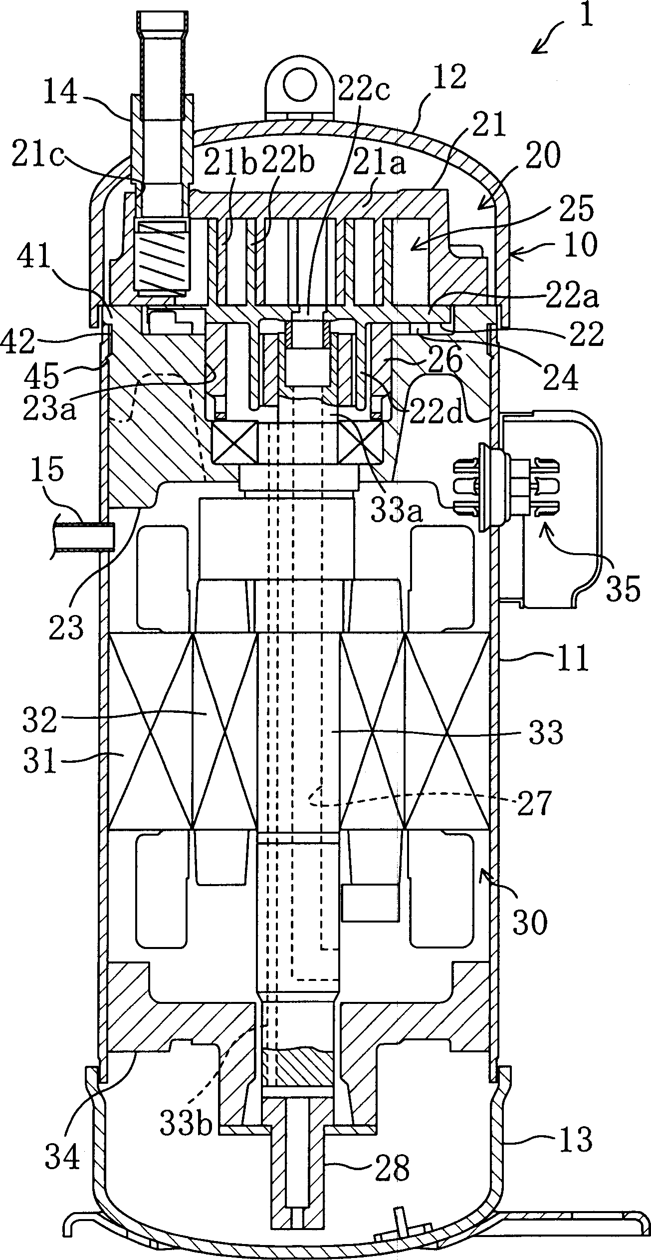
[0074] This embodiment relates to a scroll compressor. First, for the overall structure of the scroll compressor, refer to figure 1 To illustrate.
[0075] This scroll compressor (1) is used, for example, in a refrigerant circuit of a vapor compression refrigeration cycle in an air conditioner, etc., to compress a low-pressure refrigerant sucked in from the evaporator side and discharge it to the condenser side. Location. The scroll compressor (1), such as figure 1 As shown, a compression mechanism (20) and a compressor motor (30) that drives the drive mechanism of the compression mechanism (20) are provided inside the casing (10). Also, the compression mechanism (20) is arranged at the upper part of the housing (10), and the compressor motor (30) is arranged at a position slightly lower than the cylindrical part of the housing (10). Also, a connector ...
Deformed example 1
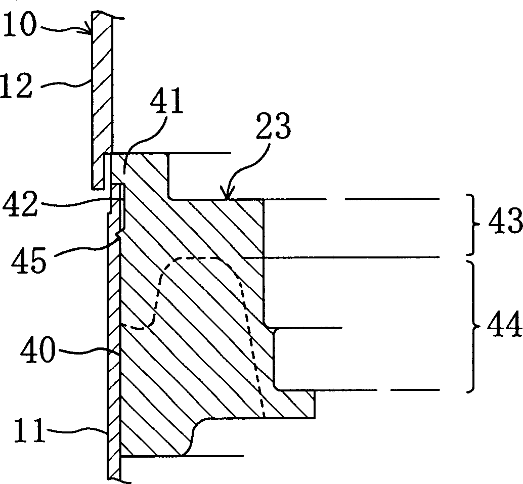
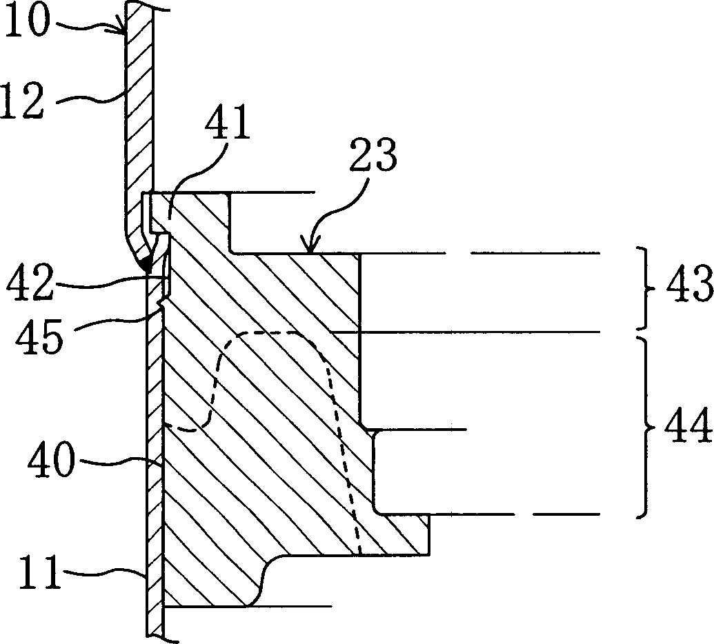
[0101] The casing (10) is formed by fitting the end cover (12) in a state where the cylindrical part (11) and the outer periphery of the frame (23) are fitted with a gap, but as Figure 4 As shown, the configuration that the end cover (12) is fitted on the inner peripheral side of the casing (10) cylinder part (11) can also be configured as an end cover ( 12) Those that can shrink due to welding. That is, as long as the circumferential groove (42) of the frame (23) is used to make the shell (10) shrink at the welding part of the cylinder part (11) and the end cover (12), the frame is strongly restricted The formation of (23) then accepts with either side of cylinder part (11) or end cap (12). In this way, the same effect as that of the first embodiment described above can also be obtained.
Deformed example 2
[0103] Modification 2 is a modification of the protruding portion.
[0104] Such as Figure 5 The example is that only the lower side end part (45a) of the protrusion part (45) that will be pressed into the cylindrical body part (11) is made into a tapered form, and the upper side end part is formed from the frame (23 ) is in the shape of standing at right angles to the peripheral surface (40). another example Figure 6 As an example, the upper side end portion (45b) of the protrusion portion (45) in the above-mentioned Embodiment 1 becomes a tapered surface form directly connected with the circumferential groove (42), and the end portion (45b) is made only An example of the tapered surface of the portion from the outer peripheral end of the protruding portion (45) to the outer peripheral surface (40) of the frame (23). In addition, another example Figure 7 For example, the end portions (45a), (45b) on the upper and lower sides of the protrusion (45) are not tapered, but ...
PUM
 Abstract
Description
Claims
Application Information
 - R&D
- Intellectual Property
- Life Sciences
- Materials
- Tech Scout
- Unparalleled Data Quality
- Higher Quality Content
- 60% Fewer Hallucinations
Browse by: Latest US Patents, China's latest patents, Technical Efficacy Thesaurus, Application Domain, Technology Topic, Popular Technical Reports.
© 2025 PatSnap. All rights reserved.Legal|Privacy policy|Modern Slavery Act Transparency Statement|Sitemap|About US| Contact US: help@patsnap.com


