Testing mask structure

A technology for testing masks and regions, which is applied in the fields of optics, instruments, and photolithography on patterned surfaces, etc. It can solve problems such as product profile degradation and inaccurate margin adjustment.

Inactive Publication Date: 2006-09-27
NAN YA TECH
View PDF0 Cites 0 Cited by
  • Summary
  • Abstract
  • Description
  • Claims
  • Application Information

AI Technical Summary

Problems solved by technology

Due to the difference in pattern density, the margin adjustment made by the test mask is inaccurate, resulting in the degradation of the profile of the final etched product

Method used


Image

  • Testing mask structure
  • Testing mask structure

Examples


Embodiment Construction

[0020] The method of the present invention will be described in detail with reference to the drawings.

[0021] According to the present invention, a novel test mask structure uses an array pattern with a ratio of 1:1 to the final product to combine with the existing test mask pattern according to a specific area ratio to achieve a desired predetermined pattern density.

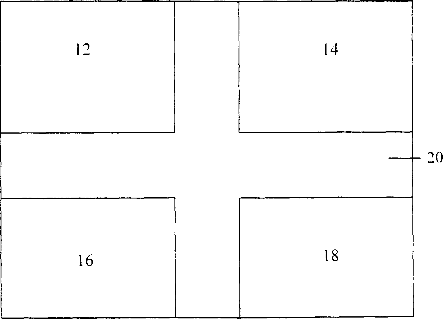
[0022] like figure 2 As shown, according to an embodiment of the present invention, the test mask structure includes array pattern regions 12, 14, 16 and 18 with a ratio of 1:1 to the line width of the final product (because the line width and line spacing are 1:1, The pattern density is 50%), and the cross region 20 in the structure is the existing test mask pattern region. By adjusting the 1:1 ratio of the total area of ​​the product array pattern areas 12 , 14 , 16 and 18 to the area of ​​the existing test mask pattern area 20 , the desired pattern density can be obtained. Its formula is as follows:

...


PUM


Abstract

A structure of test mask consists of at least one array pattern region in fixed ratio to the final product. The array pattern region has the first pattern density according to the fixed ratio and the second pattern density in mask test region. The structure regulates areas of array pattern region and mask test region according to the first and the second pattern densities for obtaining the required pattern density.

Description

technical field [0001] The present invention relates to a semiconductor manufacturing process, and more specifically to a test mask structure for improving etching precision. Background technique [0002] In the manufacturing process of semiconductor devices, the formation of various components of integrated circuits requires extensive use of mask etching techniques. However, in the steps of pattern setting, mask making, exposure, development, imaging, and final etching, due to factors such as material and actual operation errors, it is impossible to achieve the predetermined critical dimension in each step. 100% maintenance. For example, taking a pattern with a size of 180nm as an example, the line width of the initial design layout is set to be 180nm. However, in order to avoid possible errors in the future, when making the mask, the line width is maintained at the part with high pattern density 180nm, and in the medium-density part, the line width critical dimension of ...

Claims


Application Information

Patent Timeline
Patent Type & Authority Patents(China)
IPC IPC(8): H01L21/027G03F1/16G03F1/44
Inventor 吴文彬
Owner NAN YA TECH
Why Eureka
Try Eureka