


Quick Research
Generate reliable direction feasibility study reports for your R&D in just a few steps.

Technical Q&A
Discover and master advanced knowledge NOW. Basics, ideas, possibilities, all at once.

Find Solutions
As an expert in R&D theories, this can generate solutions to your technical problems instantly.

Evaluate Feasibility
Analyze your overall solution with one click, know your potential R&D risks in advance.

Monitor Landscape
Get weekly tech updates, stay abreast of the latest tech innovations and key insights.
Imaging device
The technology of an imaging device and imaging unit is applied in the directions of printing device, transportation and packaging, pile separation, etc., and can solve problems such as the lack of general characteristics of the imaging device, the trouble of connecting/disassembling the carton, etc.
- Summary
- Abstract
- Description
- Claims
- Application Information
AI Technical Summary
Problems solved by technology
Method used
Image

Examples
Embodiment 1
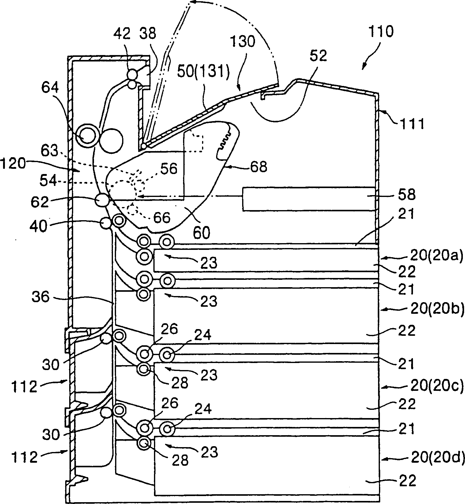
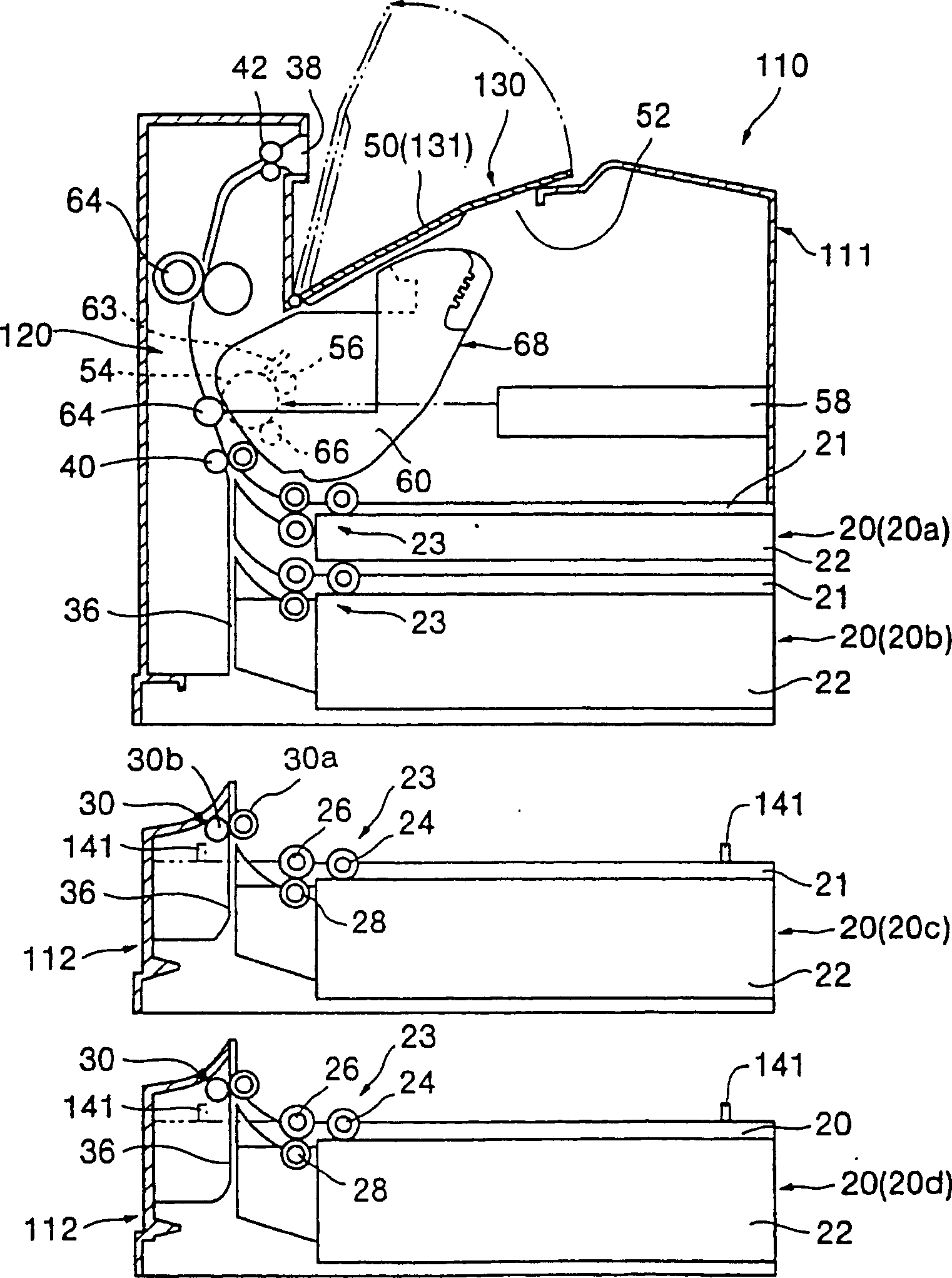
[0063] figure 2 and 3 Example 1 of the image forming apparatus used in the present invention is shown.
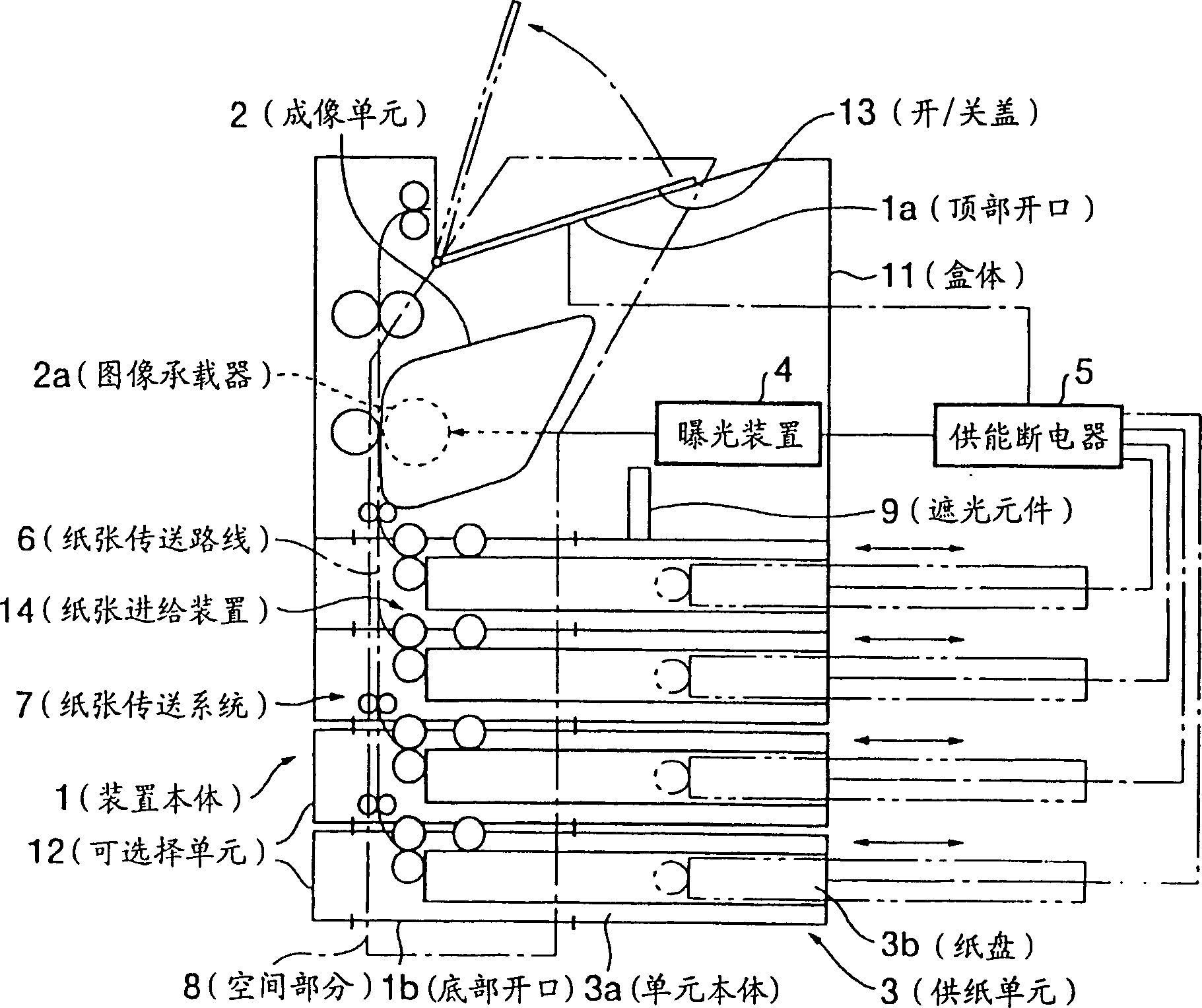
[0064] exist figure 2 and 3 Among them, the imaging device has a device body 110 forming a device housing.
[0065] In this embodiment, the device body 110 includes: a box body 111, which serves as a device housing of a standard specification; An optional unit 112 in the lower part of the box body 111 .
[0066] In this embodiment, the imaging device 120 is housed in the box 111 of the device body 110 . A paper discharge portion 130 for receiving discharged paper is provided at the top of the cassette body 111 . For example, the two-stage sheet feeding unit 20 (specifically, 20 a and 20 b ) provided as a unit of standard equipment is provided in the lower portion of the cassette body 111 , that is, below the image forming section 120 .
[0067] Inside the apparatus body 110 (cassette body 111 and optional unit 112) is provided a paper conveyance path 36 for conveyi...
Embodiment 2
[0147] Figure 11 is an explanatory diagram showing important parts of the imaging device according to Embodiment 2 of the present invention.
[0148] exist Figure 11 The basic configuration of the image forming apparatus is basically the same as that according to Embodiment 1, except for the interlock mechanism 270 for detecting attachment / detachment of the paper cassette 22 of the paper feeding unit 20 . Incidentally, the same constituent parts as in Embodiment 1 are denoted by the same reference numerals as in Embodiment 1, and thus detailed descriptions of these parts will be omitted here.
[0149] That is to say, if Figure 11 , 12A As shown in and 12B, the interlock mechanism 270 used in this embodiment includes: a rocker 272, which is arranged on one side of the device body 110 across the position of the paper cassette 22 of the paper feeding unit 20 (20a to 20d). On the side, that is: it can rotate around the fulcrum 271 located at the lower end: the joints 273 to...
PUM
 Abstract
Description
Claims
Application Information
 - R&D Engineer
- R&D Manager
- IP Professional
- Industry Leading Data Capabilities
- Powerful AI technology
- Patent DNA Extraction
Browse by: Latest US Patents, China's latest patents, Technical Efficacy Thesaurus, Application Domain, Technology Topic, Popular Technical Reports.
© 2024 PatSnap. All rights reserved.Legal|Privacy policy|Modern Slavery Act Transparency Statement|Sitemap|About US| Contact US: help@patsnap.com