Eccentricity controlling method for magnetic disk

An eccentricity control and magnetic disk technology, which is applied in the direction of aligning the magnetic track on the magnetic disk, magnetic recording, and maintaining the alignment of the head frame, can solve the problems of incorrect calculation of the eccentricity compensation signal, large fluctuations in the head position error, and deterioration of control performance, etc., to achieve shortening time, reducing control lag, and improving control performance

Inactive Publication Date: 2006-11-22
PANASONIC HEALTHCARE HLDG CO LTD
View PDF0 Cites 0 Cited by
  • Summary
  • Abstract
  • Description
  • Claims
  • Application Information

AI Technical Summary

Problems solved by technology

In addition, when the magnetic head seeks and stabilizes, the fluctuation of the magnetic head position error is large.
Therefore, in some cases, the eccentricity compensation signal cannot be calculated correctly, and in some cases, the control performance deteriorates.

Method used


Image

  • Eccentricity controlling method for magnetic disk
  • Eccentricity controlling method for magnetic disk
  • Eccentricity controlling method for magnetic disk

Examples


Embodiment Construction

[0032] Refer below Figure 1 to Figure 10 Preferred embodiments of the present invention will be described.

[0033] "First Embodiment"

[0034] Refer below Figure 1 to Figure 3 The first embodiment of the present invention will be described.

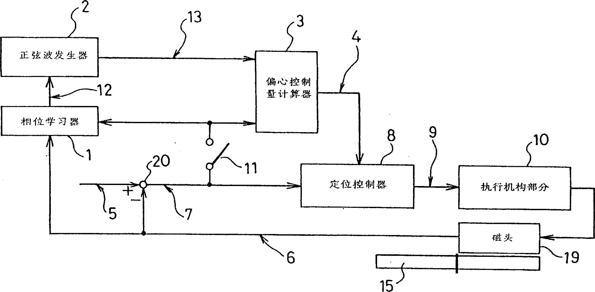
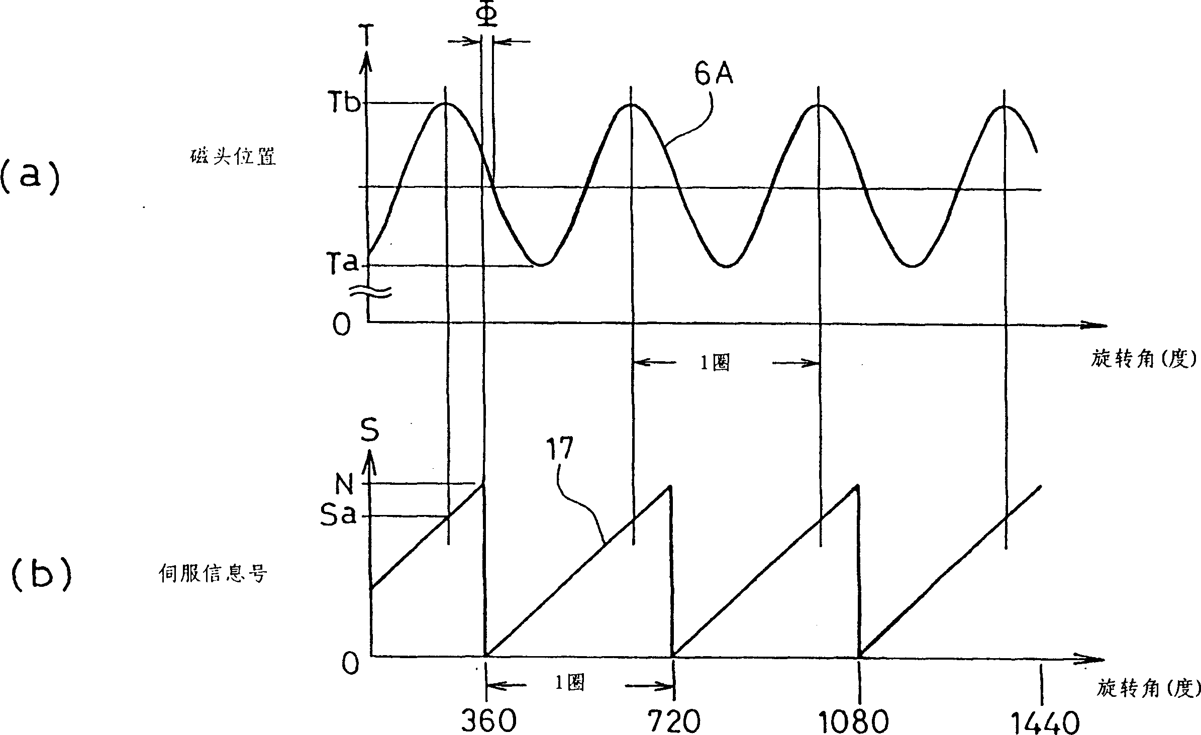
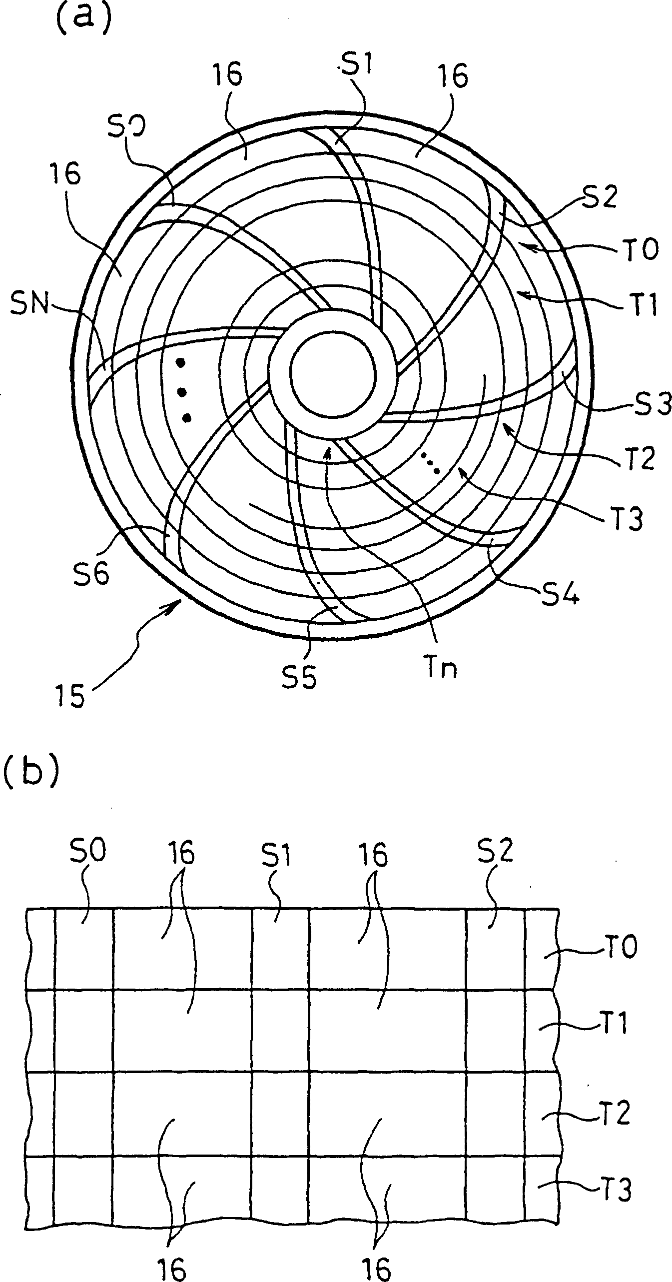
[0035] figure 1 is a block diagram of the magnetic disk device of the present invention. figure 2 (a) is a graph in which the horizontal axis represents the disk rotation angle (degrees) and the vertical axis represents the position of the magnetic head, figure 2 (b) is a graph in which the horizontal axis represents the disk rotation angle (degrees) and the vertical axis represents the servo information number. image 3 (a) is a plan view of a magnetic disk 15 having concentric tracks T0-Tn and servo information areas S0-SN, image 3 (b) is a partially enlarged view of the magnetic disk 15 showing tracks T0, T1, T2, . . . and servo information areas S0 to SN. In the following description, tracks T0 to Tn will be referred to a...


PUM


Abstract

The research object of the present invention is to calculate the control amount of the magnetic head at high speed in the eccentric control method of the magnetic disk of the magnetic disk device, so as to suppress the deterioration of the control performance due to the control lag caused by the long calculation time. Another research topic is to achieve stable control performance even when the position error of the magnetic head relative to the target position fluctuates greatly, such as when the magnetic head is seeking and when it is stable. When the magnetic disk device is started, the phase relationship between the servo information number pre-recorded on the magnetic disk 15 and the disk eccentricity is learned. When the magnetic head is positioned, according to the disk rotation frequency, the signal multiplied by the sine wave or cosine wave that compensates the phase offset by the phase weight coefficient is used as the eccentricity control amount to feed forward to compensate the eccentricity.

Description

technical field [0001] The present invention relates to a magnetic disk eccentric control method for making a magnetic head track a target track of an eccentric magnetic disk and a magnetic disk device using the eccentric control method. Background technique [0002] In a magnetic disk device, in order to use a magnetic head to record and reproduce a target track on an eccentric magnetic disk, a head control device must be provided to make the magnetic head track the target track whose distance from the center of rotation is constantly changing due to eccentricity. A general eccentric control device of a conventional magnetic head control device has a sine wave and a cosine wave generator, a digital Fourier transformer, and a multiplier. The sine wave and cosine wave generator outputs sine wave and cosine wave signals corresponding to the rotation frequency of the magnetic disk drive motor. A digital Fourier transform is used to perform digital Fourier transform on the posi...

Claims


Application Information

Patent Timeline
Patent Type & Authority Patents(China)
IPC IPC(8): G11B21/10G11B21/08G11B5/596
CPCG11B5/59627G11B21/08
Inventor 重松则夫
Owner PANASONIC HEALTHCARE HLDG CO LTD
Why Eureka
Try Eureka