
Friction clutch with predamper

A technology of transmission disc and clutch, applied in the direction of clutch, friction clutch, mechanical drive clutch, etc., can solve the problem of expensive tools and so on

Inactive Publication Date: 2006-11-29
EATON CORP
View PDF0 Cites 0 Cited by
  • Summary
  • Abstract
  • Description
  • Claims
  • Application Information

AI Technical Summary

Problems solved by technology

This is undesirable as knives are quite expensive

Method used


Image

  • Friction clutch with predamper
  • Friction clutch with predamper
  • Friction clutch with predamper

Examples


Embodiment Construction

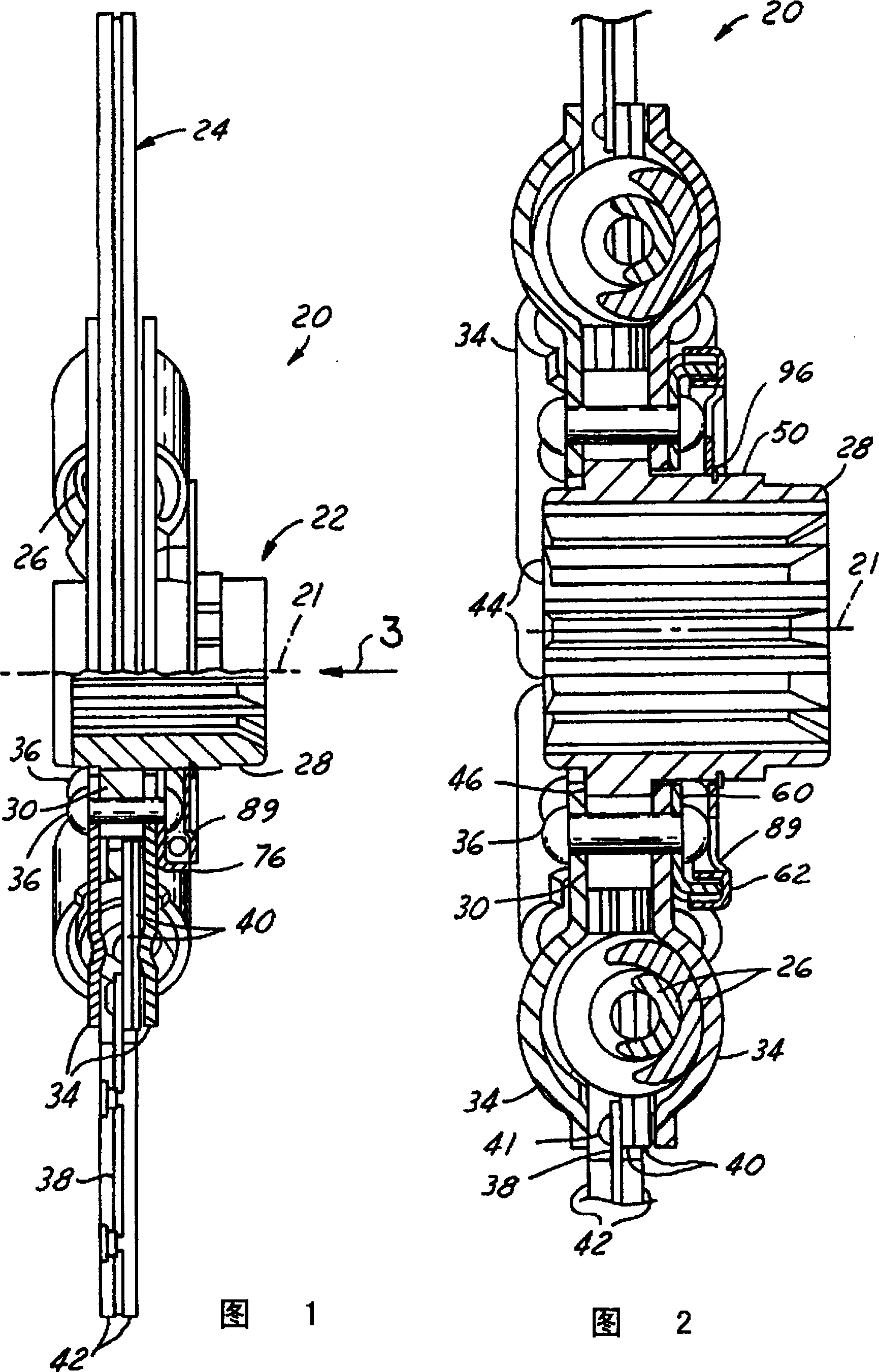
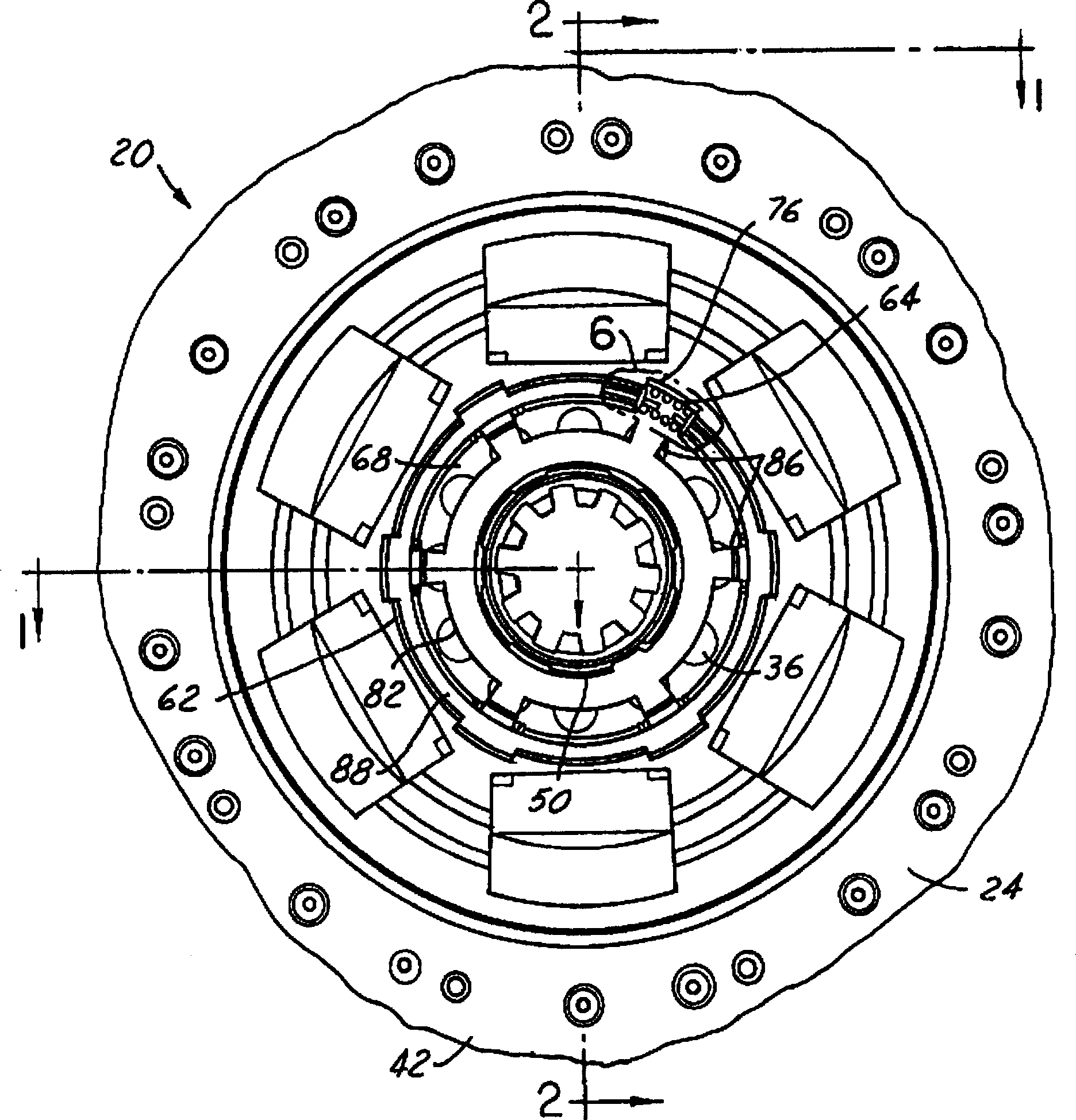
[0016] The clutch drive disc assembly 20 shown in Figure 1 includes a rotation axis 21, a sliding sleeve assembly 22, a disc assembly 24 and a number of damping or transmission springs 26, which are arranged between the sliding sleeve assembly 22 and the disc assembly 24 .

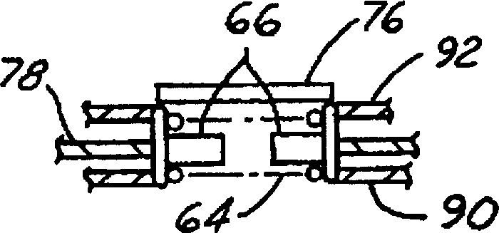
[0017] As best shown in FIGS. 2 and 4, the sliding sleeve assembly 22 includes an inner sliding sleeve 28 and an outer sliding sleeve 30. The pre-damper 32 is arranged between the inner sliding sleeve 28 and the outer sliding sleeve 30. A pair of spring plates 34 are fixed on the outer sliding sleeve 30 by rivets 36.

[0018] The disc assembly 24 includes an annular disc 38 which is fixed on a pair of overlapping annular stacks 40 by rivets 41. The stack 40 is radially arranged inside the disk 38. Opposing materials 42 are placed on each side of the disc 38 so that when it is installed in a vehicle, it frictionally engages with a clutch flywheel (not shown) and a clutch pressure plate (not shown). The stack 40...


PUM


Abstract

A clutch driven disc assembly includes an inner hub, an outer hub, an annular predamper driving element, an plurality of predamper springs, a plurality of spring caps, an annular spring plate, an annular disc assembly and a plurality of drive springs. The annular predamper driving element is rotatably fixed to the outer hub and has a planar base portion. The annular predamping driving element also has a plurality of axially extending spring retention arms and a plurality of spring engagement driving portions. The spring engagement driving portions are disposed radially inwardly of the spring retention arms. The spring retention arms define a plurality of first spring gaps in radial alignment with the spring retention arms. The annular predamper driven element is rotatably fixed to the inner hub and has an annular shoulder. The annular predamper driven element also has a plurality of axially extending spring engagement driven portions defining a plurality of second spring gaps. The second spring gaps are in radial alignment with the first spring gaps in a neutral condition. The predamper springs are disposed in the first and second spring gaps. The predamper springs are compressed with relative rotation between the predamper driving element and the predamper driven element. The annular spring plate is rotatably fixed to the outer hub. The annular disc assembly has a friction element fixed thereto. The disc assembly is mounted for relative rotation to the spring plate by a predetermined amount. The drive springs are operably disposed between the spring plate and the disc assembly.

Description

Technical field [0001] The present invention is generally related to friction clutches, and particularly to clutch drive disc pre-dampers. Background technique [0002] A clutch is a well-known device that is used to connect the crankshaft of an internal combustion engine and its flywheel and other rotational power sources to a transmission mechanism such as a gearbox, respectively. When the engine is connected to the gearbox through the clutch, the vibration is transmitted through the clutch and into the gearbox and other transmission chain components, producing undesirable noises such as gear rattling. [0003] The clutch uses long, multiple compression damping springs between the clutch slip sleeve connected to the input shaft of the gearbox and the clutch disc connected to the engine flywheel. These springs are generally arranged in a spring cover positioned around the circumference of the clutch sleeve. The compression of the damping spring is restricted by the stopper, whic...

Claims


Application Information

Patent Timeline
Patent Type & Authority Patents(China)
IPC IPC(8): F16D13/38F16F15/121F16F15/12F16F15/123
CPCF16F15/1238F16F15/1203
Inventor D·V·戈彻诺尔
Owner EATON CORP
Learn More