Cooling structure of communication device
A technology of machines and communication circuits, applied in cooling/ventilation/heating renovation, electrical equipment structural parts, electrical components, etc., can solve problems such as inability to guarantee electrical characteristics
- Summary
- Abstract
- Description
- Claims
- Application Information
AI Technical Summary
Problems solved by technology
Method used
Image
Examples
Embodiment 1
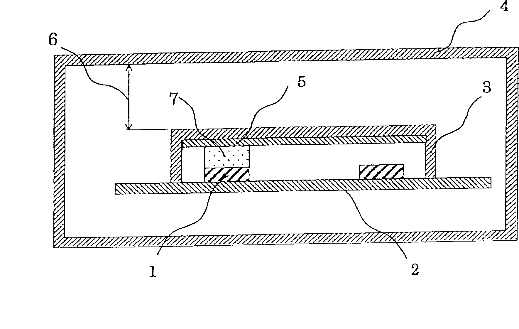
[0026] Fig. 1 is a cross-sectional configuration diagram showing the main configuration of a portable communication device according to Embodiment 1 of the present invention. In this figure, 1 is a heat generating element (hereafter referred to as a heat generating element), 2 is a printed circuit board on which a communication circuit having a heat generating element 1 is mounted, and 3 is a circuit board for suppressing the incidence of noise caused by electromagnetic waves from the outside, covering communication The resin shielding case 4 of the circuit is a housing for accommodating the shielding case 3 and the printed circuit board 2 . 5 is a heat dissipation fin (thermal diffusion member) installed along the inner wall of the shield box 3 for thermal diffusion in the surface direction. As the material of the heat sink 5, in addition to metal sheets with high thermal conductivity, such as Al (thermal conductivity: 236W / mK) and copper (thermal conductivity: 403W / mK), it i...
Embodiment 2
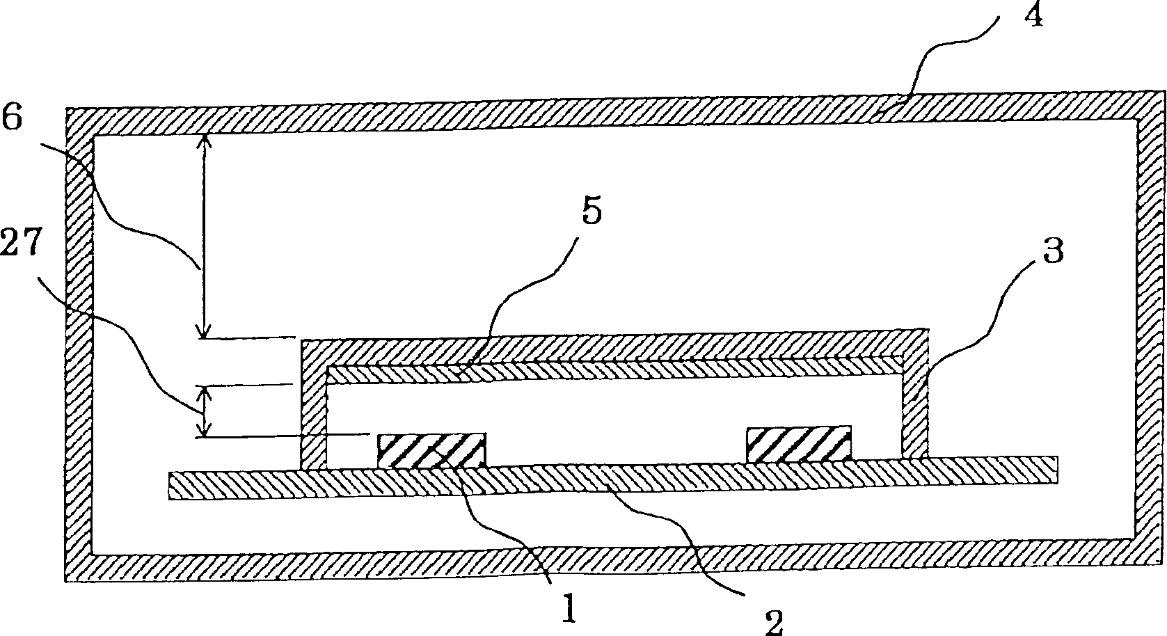
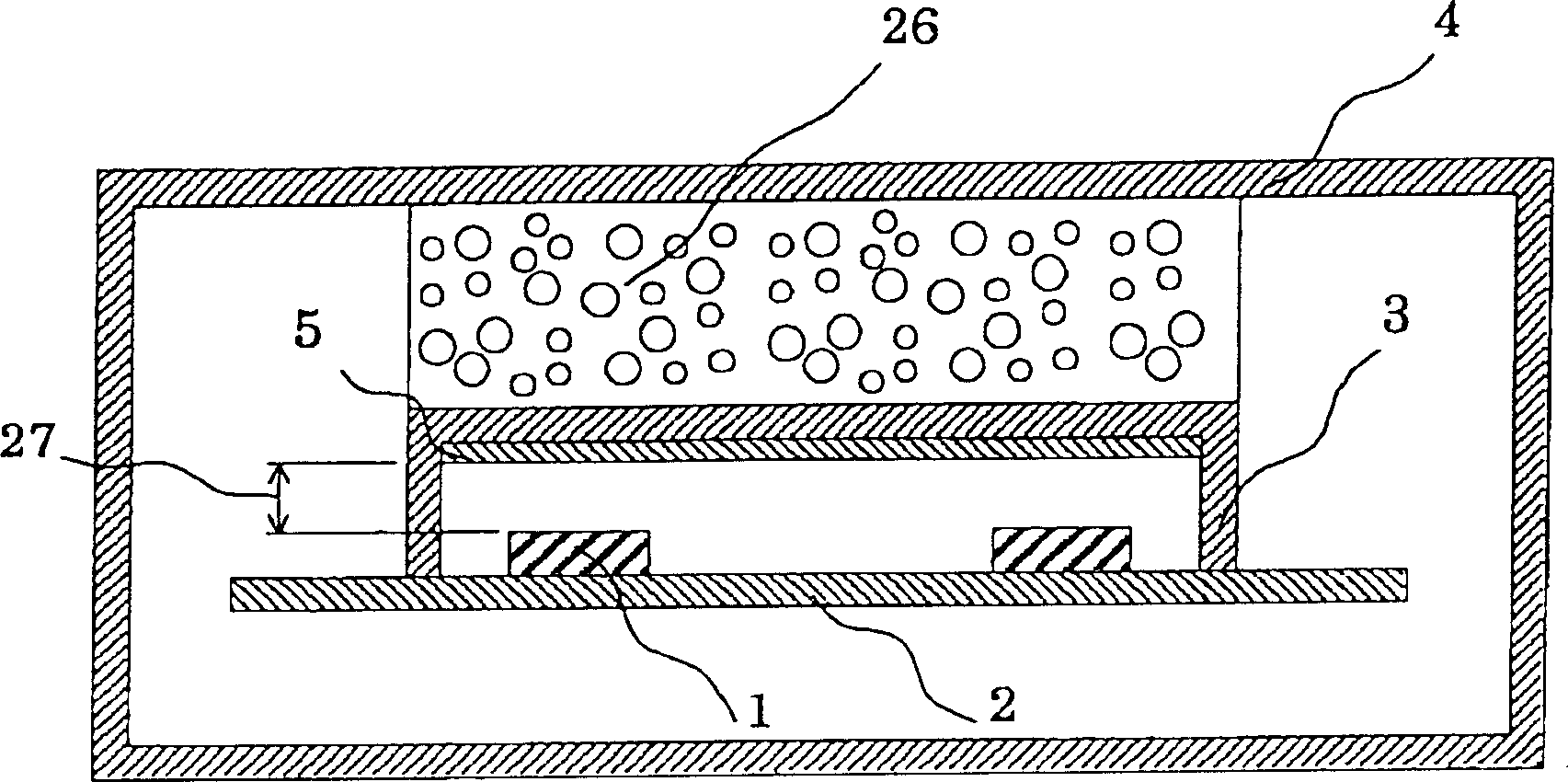
[0064] Fig. 2 is a cross-sectional configuration diagram showing the main configuration of a portable communication device according to Embodiment 2 of the present invention, and Fig. 3 is a cross-sectional configuration diagram showing the main configuration of another portable communication device according to Embodiment 2 of the present invention. 2 is an example of ensuring an air layer as the heat insulating layer 6, and FIG. 3 is an example of providing a foam material 26 as the heat insulating layer 6.
[0065] In the 2nd figure, among the 3rd figure, 27 is an air layer. In Embodiment 2, no thermally conductive sheet 7 is provided between the heat sink 5 and the heating element 1 , and an air layer 27 is formed between the heat sink 5 and the heat generating element 1 . When the calorific value of the heating element 1 is small, as long as the heat sink 5 is installed on the inner wall of the shielding box 2, the temperature of the heating element can be fully reduced b...
Embodiment 3
[0068] Fig. 4 is a cross-sectional configuration diagram showing the main configuration of a portable communication device according to Embodiment 3 of the present invention. In this figure, 33 is a metal shielding box. In this embodiment, the shielding box is made of metal material, so that the metal shielding box 33 has the function of the heat sink 5 in the first embodiment. The thermal conductive sheet 7 is installed between the heating element 1 and the inner wall of the metal shielding box, and the air layer 6 is between the metal shielding box 33 and the housing 4 .
[0069] By doing so, the same effect as that of the first embodiment is obtained, and since the attachment of the heat sink can be omitted, the effect of reducing the assembly cost can be obtained.
PUM
| Property | Measurement | Unit |
|---|---|---|
| Thermal conductivity | aaaaa | aaaaa |
| Thermal conductivity | aaaaa | aaaaa |
| Thickness | aaaaa | aaaaa |
Abstract
Description
Claims
Application Information
 - R&D
- Intellectual Property
- Life Sciences
- Materials
- Tech Scout
- Unparalleled Data Quality
- Higher Quality Content
- 60% Fewer Hallucinations
Browse by: Latest US Patents, China's latest patents, Technical Efficacy Thesaurus, Application Domain, Technology Topic, Popular Technical Reports.
© 2025 PatSnap. All rights reserved.Legal|Privacy policy|Modern Slavery Act Transparency Statement|Sitemap|About US| Contact US: help@patsnap.com


