Catalyst for fuel cell and its fuel cell

A fuel cell and catalyst technology, applied in battery electrodes, circuits, electrical components, etc., can solve the problem of low catalyst dispersion, achieve high dispersion, high active area, and reduce potential drop.

Inactive Publication Date: 2006-12-20
HONG FU JIN PRECISION IND (SHENZHEN) CO LTD +1
View PDF2 Cites 0 Cited by
  • Summary
  • Abstract
  • Description
  • Claims
  • Application Information

AI Technical Summary

Problems solved by technology

[0007] In order to solve the problem of low catalyst dispersion in the prior art, the object of the present invention is to provide a highly dispersed fuel cell catalyst

Method used


Image

  • Catalyst for fuel cell and its fuel cell
  • Catalyst for fuel cell and its fuel cell

Examples


Embodiment Construction

[0014] The present invention will be further described in detail below in conjunction with the accompanying drawings.

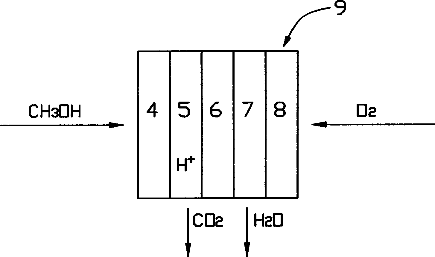
[0015] see figure 1 , the fuel cell 9 of the preferred embodiment of the present invention comprises gas diffusion layers 4 and 8, positive pole 5, negative pole 7, proton exchange membrane 6, wherein, proton exchange membrane 6 is positioned between positive pole 5 and negative pole 7, gas diffusion layer 4 and 8 are located outside the positive electrode 5 and the negative electrode 7 respectively.

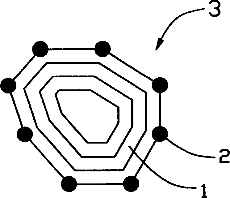
[0016] Please also see figure 2 , both the positive electrode 5 and the negative electrode 7 are composed of a catalyst 3, the catalyst 3 includes carbon nanospheres 1 and catalyst metal 2, and the catalyst metal 2 is atomically embedded on the corners or turning parts of the carbon nanospheres 1, in this embodiment, The catalyst metal 2 is metal platinum.

[0017] Nano-carbon sphere 1 is a polyhedral carbon cluster composed of multilayer graphite layers wi...


PUM

PropertyMeasurementUnit
diameteraaaaaaaaaa

Abstract

This invention provides a catalyst used in a fuel battery including nm carbon spheres and catalyst metal inlaid on the corner or bend part in the atomic way. Besides, it also provides a fuel battery including a gas diffusion layer, a positive, negative and proton exchange film, the positive and negative are formed by said catalyst at stable state and high dispersity. The fuel battery can get rather high active area of the catalyst which is good for battery reaction.

Description

【Technical field】 [0001] The invention relates to a fuel cell catalyst and its fuel cell, in particular to a highly dispersed fuel cell catalyst and its fuel cell. 【Background technique】 [0002] As the world's population and human activities grow, humans are often limited by the ability to supply electrical energy to support their various activities. Fuel cells provide a solution to this difficulty by generating electricity directly from chemical raw materials such as oxygen and methanol, that is, fuel cells generate electricity electrochemically, using methanol as fuel, and generating electricity after reacting with oxygen and a small amount of Heat energy, so it is also called cold combustion. Moreover, the product discharged after the fuel cell generates electricity is water (H 2 O), in line with environmental protection standards, to solve the inherent pollution problems of the direct combustion process. Especially when the equipment requires low power and long-term ...

Claims


Application Information

Patent Timeline
Patent Type & Authority Patents(China)
IPC IPC(8): H01M4/90H01M4/92
CPCY02E60/50
Inventor 黄全德黄文正
Owner HONG FU JIN PRECISION IND (SHENZHEN) CO LTD
Why Eureka
Try Eureka