
Spinneret

A technology of spraying and spraying boards, which is applied in the direction of spray head components, textiles and papermaking, which can solve the problems of inserting in a severe expansion shell, influence, and unfavorable accuracy of coordination, so as to improve automatic automatic automatic automatic accuracy The effect of sealing effect, small thermal expansion coefficient

Inactive Publication Date: 2007-01-24
SAURER GMBH & CO KG
View PDF7 Cites 2 Cited by
  • Summary
  • Abstract
  • Description
  • Claims
  • Application Information

AI Technical Summary

Problems solved by technology

This known spinneret has the disadvantage that the inner parts of the spinneret are directly inserted in a strongly expanding housing part
Therefore, the inner parts must be inserted with corresponding clearances taking thermal expansion into account, but this has a detrimental effect on the required fit accuracy for sealing the joints

Method used


Image

  • Spinneret
  • Spinneret
  • Spinneret

Examples


Embodiment Construction

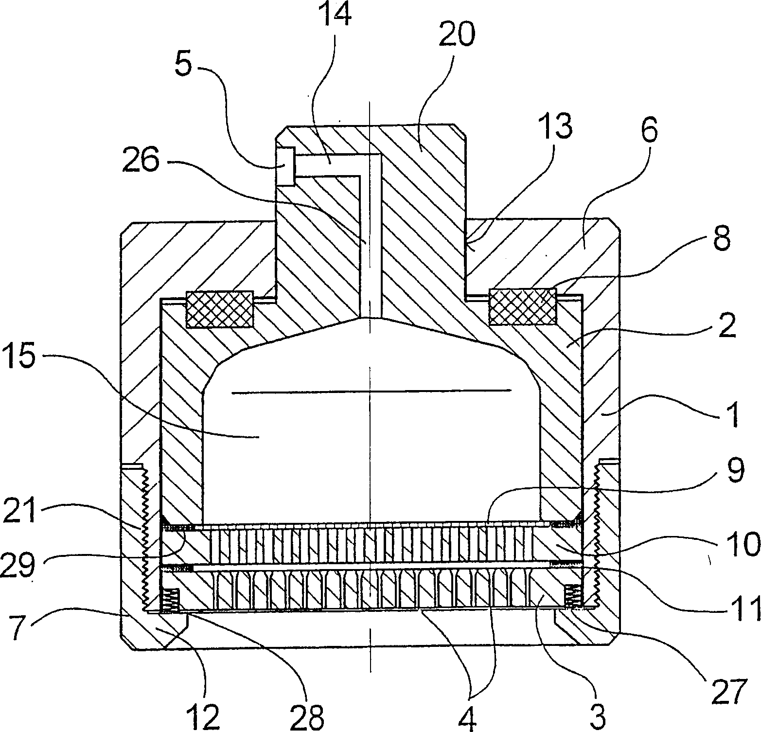
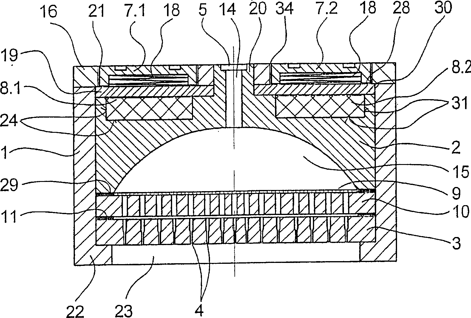
[0027] figure 1 shows a cross-sectional view of a first embodiment of a spinneret according to the invention. The spinneret has a cylindrical housing 1 which is delimited at the end by a base plate 6 in the upward direction. There is a hole 13 in the center of the bottom plate 6 . A boss 20 inserted into the inlet part 2 of the housing 1 protrudes through the opening 13 in the housing base 6 . An expansion body 8 in the form of an expansion ring is arranged between the inlet part 2 and the housing bottom 6 .

[0028] In this case, the inlet part 2 is supported on the housing base 6 via the annular expansion body 8 . The inlet part 2 has a melt inlet 5 on a boss 20 protruding outside the housing 1 , which communicates via an inlet channel 14 and a melt channel 26 with a distribution chamber 15 in the inlet part 2 . A filter assembly 9 , a perforated plate 10 and a spinneret 3 are connected to the end faces of the inlet part 2 in the housing 1 . An outer circumferential sea...


PUM

PropertyMeasurementUnit
melting pointaaaaaaaaaa

Abstract

A spinneret assembly for melt spinning a plurality of strand-like filaments, which includes a plurality of internal parts composed of at least one inlet component 2 and a spinneret plate 3 which are braced relative each other in a housing 1 by a supporting means. The inlet component 2 forms a melt inlet 5, and the spinneret plate 3 forms a melt outlet by means of a plurality of spin holes 4. To achieve during operation a self-sealing between the internal parts, the invention provides for arranging an expansion body 8 between the housing 1 and one of the internal parts. The expansion body 8 is formed of a material which has a higher thermal expansion coefficient than the housing material, and it generates, upon being heated, a pressure force inside the housing which provides for a self-sealing bracing of the internal parts.

Description

technical field [0001] The invention relates to a spinneret for melt-spinning a plurality of filaments / filaments in the form of strips, the spinneret has a housing, a plurality of internal parts formed by at least one inlet piece and a spinneret, A screw arrangement, wherein the inner parts are inserted into the housing and fixed to each other by means of the screw arrangement, wherein the inlet piece forms a melt inlet, and the spinneret forms the melt outlet by means of a plurality of spinneret holes. Background technique [0002] A spinneret of this type is known, for example, from DE 199 32 852 A1. [0003] The known spinneret has a housing for receiving a spinneret plate, an orifice plate, a filter assembly, and an inlet piece. The spinneret plate, orifice plate and inlet piece are loaded into the shell and fixed inside the shell by a screw device. The inner parts of the housing are made of a material having a higher coefficient of thermal expansion than the material ...

Claims


Application Information

Patent Timeline
Patent Type & Authority Patents(China)
IPC IPC(8): D01D4/00D01D4/08B29C48/345
CPCD01D4/00
Inventor B·基希霍夫
Owner SAURER GMBH & CO KG
Learn More