Double-layer sealing bypass valve with air-tight device

A double-layer sealing and bypass valve technology, which is used in the field of air pollutant treatment and environmental protection, can solve the problems of easy dust accumulation on the sealing surface, large space occupation, short service cycle, etc., and can increase the sealing contact area and the sealing contact area. The effect of increasing and improving the sealing effect

Active Publication Date: 2017-08-22
MCC ENERGY SAVING & ENVIRONMENTAL PROTECTION +1
View PDF10 Cites 3 Cited by
  • Summary
  • Abstract
  • Description
  • Claims
  • Application Information

AI Technical Summary

Problems solved by technology

[0002] At present, there are many types of valves used for off-line maintenance of dust collectors, and there are many types of bypass valves. These devices have disadvantages, such as: poor sealing, unable to meet ultra-low emission requirements; complex structure, large space occupation, resulting in high investment and poor operation. The maintenance workload is heavy; the sealing surface is easy to accumulate dust and age, causing the valve to leak easily and the service life is short.

Method used


Image

  • Double-layer sealing bypass valve with air-tight device
  • Double-layer sealing bypass valve with air-tight device
  • Double-layer sealing bypass valve with air-tight device

Examples


Embodiment Construction

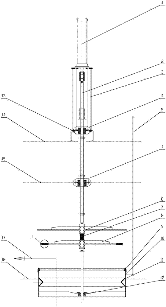
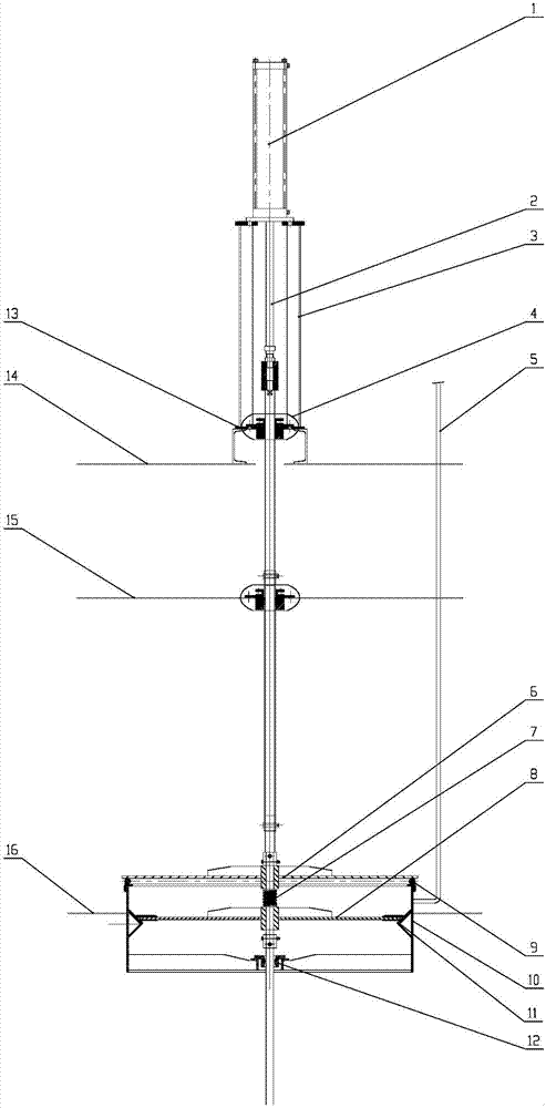
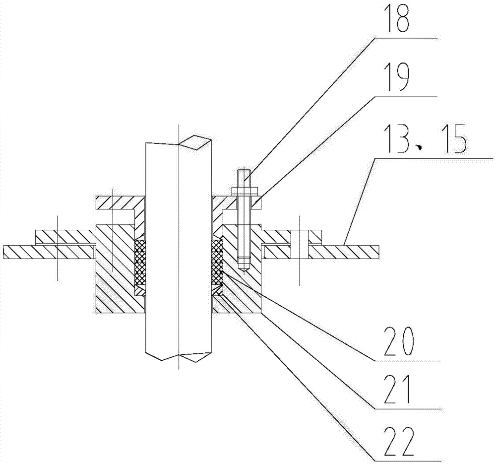
[0040] Such as Figure 1-4As shown, a double-layer sealed bypass valve with an airtight device includes a cylinder 1, a connecting rod 2, a valve body 3, an airtight pipeline 5, a valve plate 6, and a compression elastic element 7, preferably a compression spring , valve plate two 8, hollow sealing ring 9, air duct 10 and inclined plane sealing surface 11; wherein, valve body 3 is installed on the air duct top plate 14 through valve base 14, valve plate one 6, compression elastic element 7 and valve plate two 8 is installed on the connecting rod 2, the cylinder 1 is installed on the valve body 3, the connecting rod 2 is connected with the cylinder 1, and the connecting rod 2 drives the valve plate 1 6, the compression elastic element 7 and the valve plate 2 under the force of the cylinder 1 8 moves up and down, the hollow sealing ring 9 and the inclined sealing surface 11 are installed on the air duct 10, the valve plate 1 6 can cooperate with the hollow sealing ring 9, and th...


PUM


Abstract

The invention relates to a double-layer sealing bypass valve with an air-tight device. A valve body (3) is mounted on an air flue top plate (14) through a valve base (13), a filler sealing device (4) is mounted on the valve base (13) and an upper air flue partition plate (15), and a first valve plate (6), a compression elastic element (7) and a second valve plate (8) are mounted on a connecting rod (2); an air cylinder (1) is mounted on the valve body (3), the connecting rod (2) is connected with the air cylinder (1) and penetrates through the filler sealing device (4) under acting force of the air cylinder (1) to drive the first valve plate (6), the compression elastic element (7) and the second valve plate (8) to vertically move; and a hollow sealing ring (9), an inclined face sealing face (11) and a guiding device (12) are mounted on an air pipe (10) to form a double-layer sealing structure, an air-tight pipeline (5) communicates with the air pipe (10), and under the valve-closed state, compressed air enters the enclosed space formed by the air pipe (10), the first valve plate (6) and the second valve plate (8) through the air-tight pipeline (5) so as to form a positive-pressure chamber, and thus the air-tight effect is achieved. According to the double-layer sealing bypass valve with the air-tight device, zero leakage of an air flue bypass pipeline can be achieved, which is a prerequisite for dust removal equipment to achieve ultra-clean emission.

Description

technical field [0001] The invention relates to a double-layer sealed bypass valve device with an airtight device, which belongs to the technical field of air pollutant treatment and environmental protection. It is mainly used in the field of industrial waste gas treatment and ultra-clean emission, and can also be used in metallurgy, electric power, chemical industry, building materials, food processing and other fields. Background technique [0002] At present, there are many types of valves used for off-line maintenance of dust collectors, and there are many types of bypass valves. These devices have disadvantages, such as: poor sealing, unable to meet ultra-low emission requirements; complex structure, large space occupation, resulting in high investment and poor operation. The maintenance workload is heavy; the sealing surface is easy to accumulate dust and age, causing the valve to leak easily and the service life is short. Contents of the invention [0003] The obje...

Claims


Application Information

Patent Timeline
Patent Type & Authority Applications(China)
IPC IPC(8): F16K1/36F16K1/46F16K1/32F16K31/12F16K37/00F16K41/02F16K41/08
CPCF16K1/32F16K1/36F16K1/46F16K31/12F16K37/0041F16K41/02F16K41/08
Inventor 张义文罗宏晶张鹏李鹏飞李昆陈玲
Owner MCC ENERGY SAVING & ENVIRONMENTAL PROTECTION
Why Eureka
Try Eureka