Thread feeding device comprising spring stop for thread detecting

A technology for stopping devices and feeding devices, which can be used in transportation and packaging, textiles and papermaking, weft knitting, etc., and can solve problems such as weakening of the function of yarn feeding devices

Inactive Publication Date: 2007-01-24
MEMMINGER IRO GMBH
View PDF4 Cites 2 Cited by
  • Summary
  • Abstract
  • Description
  • Claims
  • Application Information

AI Technical Summary

Problems solved by technology

Otherwise, the effect of the yarn feeding device will be weakened

Method used


Image

  • Thread feeding device comprising spring stop for thread detecting
  • Thread feeding device comprising spring stop for thread detecting
  • Thread feeding device comprising spring stop for thread detecting

Examples


Embodiment Construction

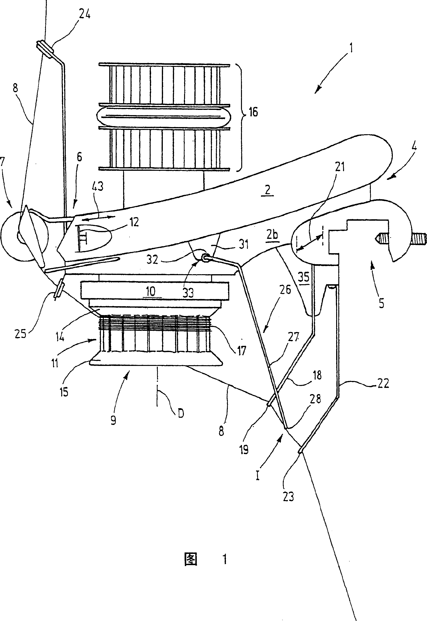
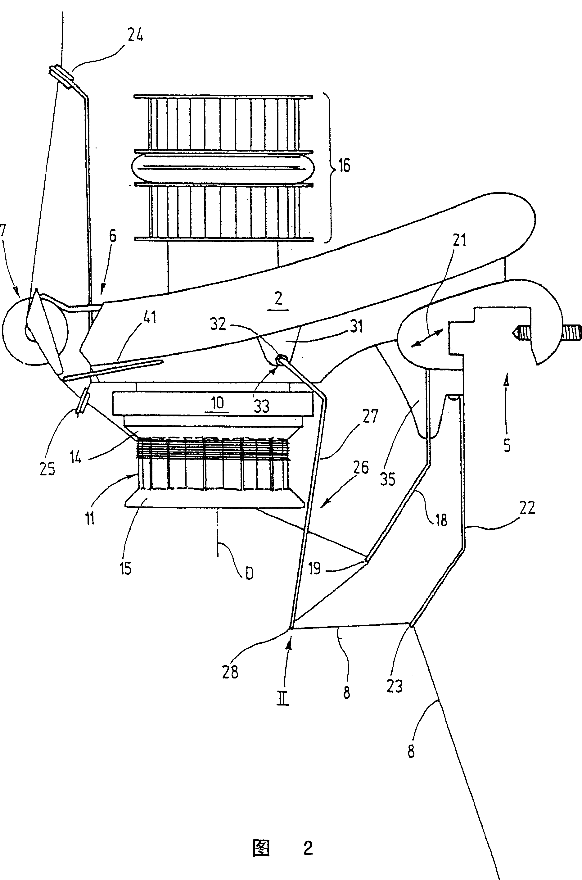
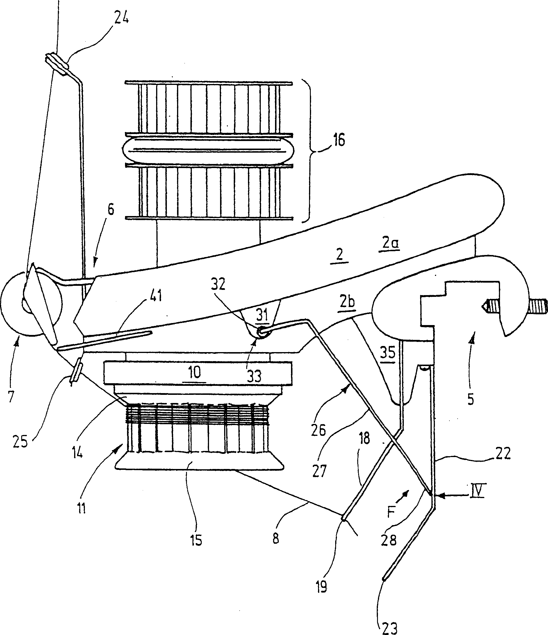
[0028] In Fig. 1, a yarn feeding device 1 is shown, the housing 2 of which acts as a central support. At one end 4 it is provided with a fastening clip 5 for fastening to a knitting machine or similar thread using machine, while at the opposite end 6 a thread stopper 7 is arranged. This yarn stop stops the yarn 8 running past it by non-positive engagement.

[0029] Between the ends 4, 6 there is a vertical shaft rotatably supported on the housing 2 about the axis of rotation D, and at its lower end there is a yarn feeding wheel 9 which has a ring at the top 10. This ring is preferably a deep elongated sheet metal part. The outer peripheral surface 11 of the sheet metal part is closed and shaped, while the upper and lower edges 14, 15 are each tapered. One or more pulleys 16 are used to drive the yarn feed wheel 9, the pulleys 16 above the housing 2 being connected to the shaft.

[0030]The yarn feeding wheel 9 forms a kind of advancing device for feeding the yarn 8 accordi...


PUM


Abstract

The invention relates to a thread feeding device (1) comprising one or more thread detector levers (26) which are arranged in displaceable manner in a housing (2). The thread detecting lever (26) is displaceable between an operating position I and a response position II. In the operating position I the lug thereof (28) which forms the means for detecting the thread, is approximately aligned with the thread guiding element, for example the lugs (19, 23) of the thread guiding members (18, 22). Approximately upstream from the operation position I, the thread detecting device (26) encounters the stop thereof beyond which it can no longer be displaced by the thread (8). In order to improve the accessibility to the thread guiding elements (19, 23), particularly when inserting and threading threads, the thread detecting lever (26) stop is elastic. The lower end (28) of the thread detecting lever (26) can be displaced manually in an upward direction beyond the stop in order to create a free space between the thread guiding elements (19, 23).

Description

technical field [0001] The invention relates to a yarn feeding device with a yarn delivery device for feeding yarn according to a given value, with at least one yarn guide element for guiding the yarn delivered by the yarn delivery device For a given yarn, there is at least one yarn detecting device supported by a vertical bar, the yarn detecting device is placed next to the yarn guiding element and is movably supported between an operating position and a response position and passes the yarn The thread is held in the operating position, the movement of the yarn detecting device in or beside the operating position being limited by the stop means. . Background technique [0002] The known yarn feeding device has a yarn feeding wheel on which the yarn is wound, on the one hand said feeding wheel is used to continuously draw the yarn from the yarn bobbin Thread, and on the other hand is used to provide this yarn to yarn using station, for example knitting machine. Such a yar...

Claims


Application Information

Patent Timeline
Patent Type & Authority Patents(China)
IPC IPC(8): D04B15/48B65H51/20
CPCD04B15/48
Inventor E·莱恩斯A·霍尔瓦斯R·考夫曼
Owner MEMMINGER IRO GMBH
Why Eureka
Try Eureka