Flash lamp unit

A flash device and flash light-emitting technology, applied in lighting devices, light sources, optics, etc., can solve the problems of uneven light distribution and insufficient light quantity, etc.

Inactive Publication Date: 2007-01-24
OLYMPUS OPTICAL CO LTD
View PDF6 Cites 0 Cited by
  • Summary
  • Abstract
  • Description
  • Claims
  • Application Information

AI Technical Summary

Problems solved by technology

[0004] The present invention is proposed to solve the above-mentioned existing problems, and the purpose is to provide a flashlight device that does not cause problems such as uneven light distribution and insufficient light quantity, and can improve the orientation characteristics of the discharge tube.

Method used


Image

  • Flash lamp unit
  • Flash lamp unit
  • Flash lamp unit

Examples


Embodiment Construction

[0014] Hereinafter, embodiments of the present invention will be described with reference to the drawings.

[0015] First, a first embodiment of the strobe device of the present invention will be described.

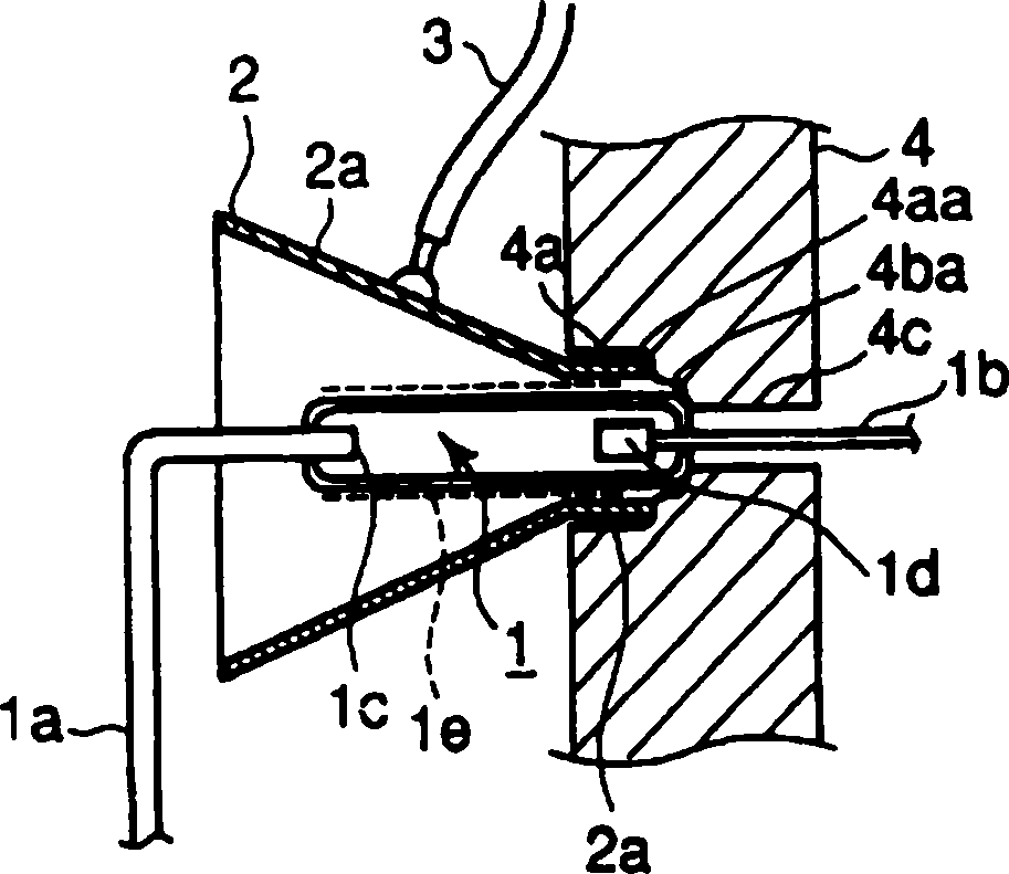
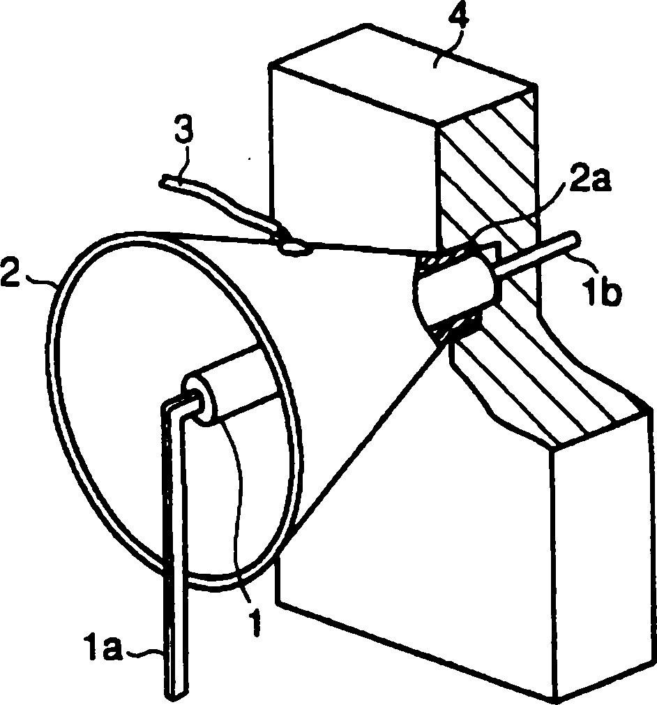
[0016] figure 1 It is a sectional view showing the structure of the strobe device of the present invention. figure 2 It is a perspective view showing the light emitting part of the strobe device in partial cross section.

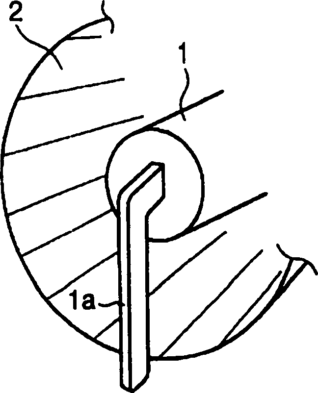
[0017] A xenon tube 1, which is a flash discharge tube, has xenon gas enclosed therein, and has terminals 1a and 1b extending outward from both ends thereof. The terminal 1a is formed to extend toward the direction of light irradiation, and the terminal 1b is formed to extend toward the fixing member 4 of the main body. The terminal 1a is bent at a substantially right angle with respect to the xenon tube 1, and is electrically connected to an unillustrated lead wire or a substrate. On the other hand, the terminal 1b extends linearly with respect to...


PUM


Abstract

Provided is a stroboscope apparatus where an orientation characteristic of a discharge tube is improved without occurrence of light distribution unevenness and light quantity lack. In the stroboscope apparatus, light emitted from a xenon tube 1 having a discharge emission part and terminals 1a and 1b is reflected toward a prescribed direction by a reflecting umbrella 2. A transparent electrode 1e is applied on an outer surface of the xenon tube 1 between the discharge luminous part and the terminals 1a and 1b. A trigger voltage is applied to the xenon tube 1 through the transparent electrode 1e.

Description

technical field [0001] The present invention relates to camera flash units including digital cameras. Background technique [0002] In the past, in the strobe device that adopts parabolic shape reflector, as the method for applying trigger voltage to discharge tube, known has, for example, disclosed in Japanese Patent Application Laid-Open No. 63-48537, using an elastic material and a miniature spherical discharge tube. The way the trigger voltage is applied due to head contact. [0003] However, in the trigger voltage application method disclosed in Japanese Patent Application Laid-Open No. 63-48537 mentioned above, an elastic material for applying a trigger circuit is disposed between the microspherical discharge tube and the subject. Therefore, the light emitted from the discharge tube is blocked by the elastic material, causing problems such as uneven light distribution and insufficient light quantity. Contents of the invention [0004] The present invention is propo...

Claims


Application Information

Patent Timeline
Patent Type & Authority Patents(China)
IPC IPC(8): G03B15/05G03B15/02G03B15/03H01J61/54H05B41/32
Inventor 土田启一三上和生
Owner OLYMPUS OPTICAL CO LTD
Why Eureka
Try Eureka