
Luminous tube array display equipment

A technology for display equipment and light-emitting tubes, which is applied to alternating current plasma display panels, discharge tubes, cold cathode tubes, etc., can solve the problems of film cracking, poor ductility of transparent electroplating conductive films, etc., and achieve the effect of improving efficiency

Inactive Publication Date: 2007-02-07
SHINODA PLASMA
View PDF2 Cites 0 Cited by
  • Summary
  • Abstract
  • Description
  • Claims
  • Application Information

AI Technical Summary

Problems solved by technology

[0005] In addition, due to the poor ductility of the transparent plating conductive film, when the film is formed on a flexible PET (polyethylene terephthalate) substrate, etc., bending of the substrate can cause the film to crack

Method used


Image

  • Luminous tube array display equipment
  • Luminous tube array display equipment
  • Luminous tube array display equipment

Examples


Embodiment Construction

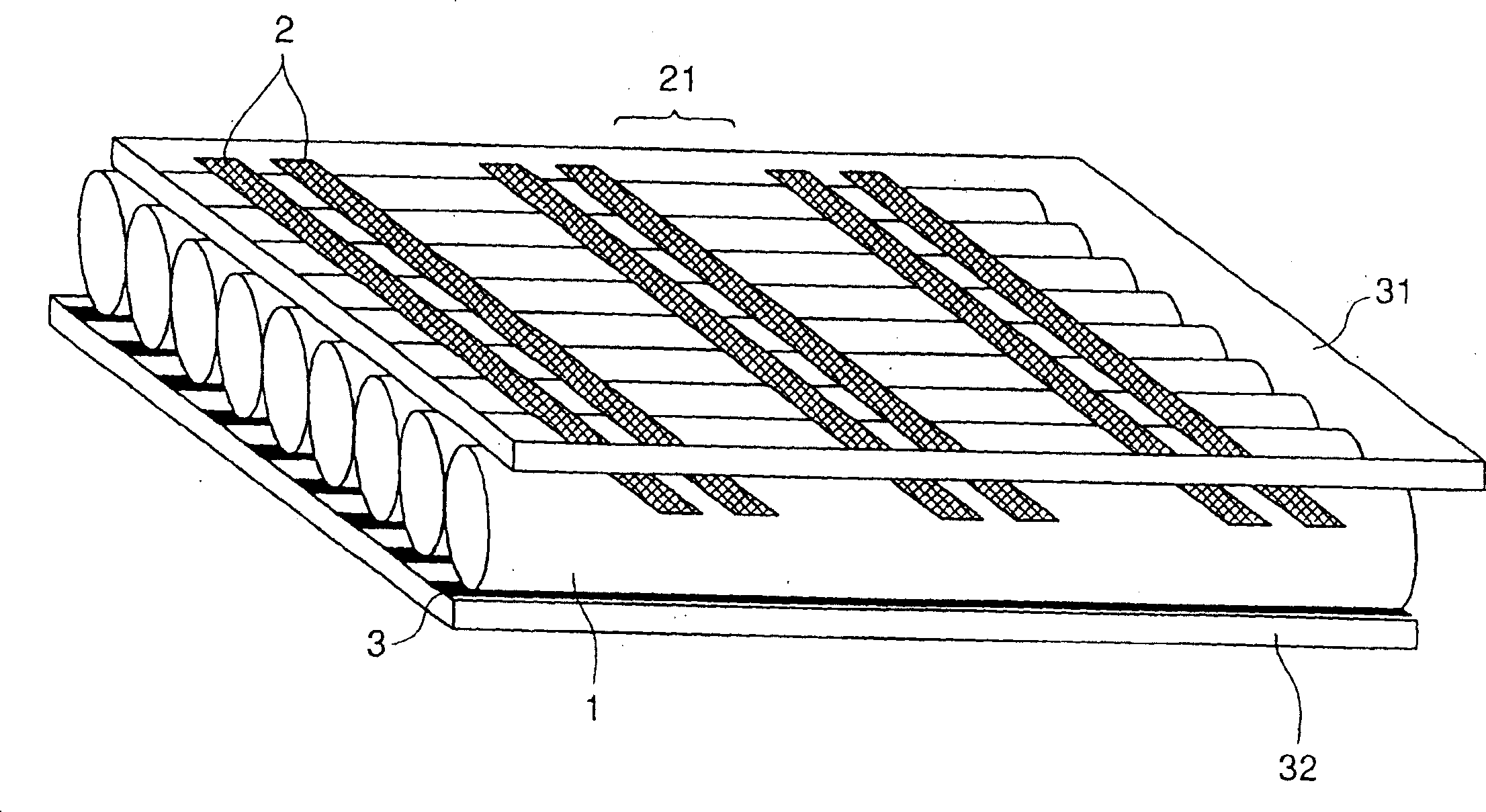
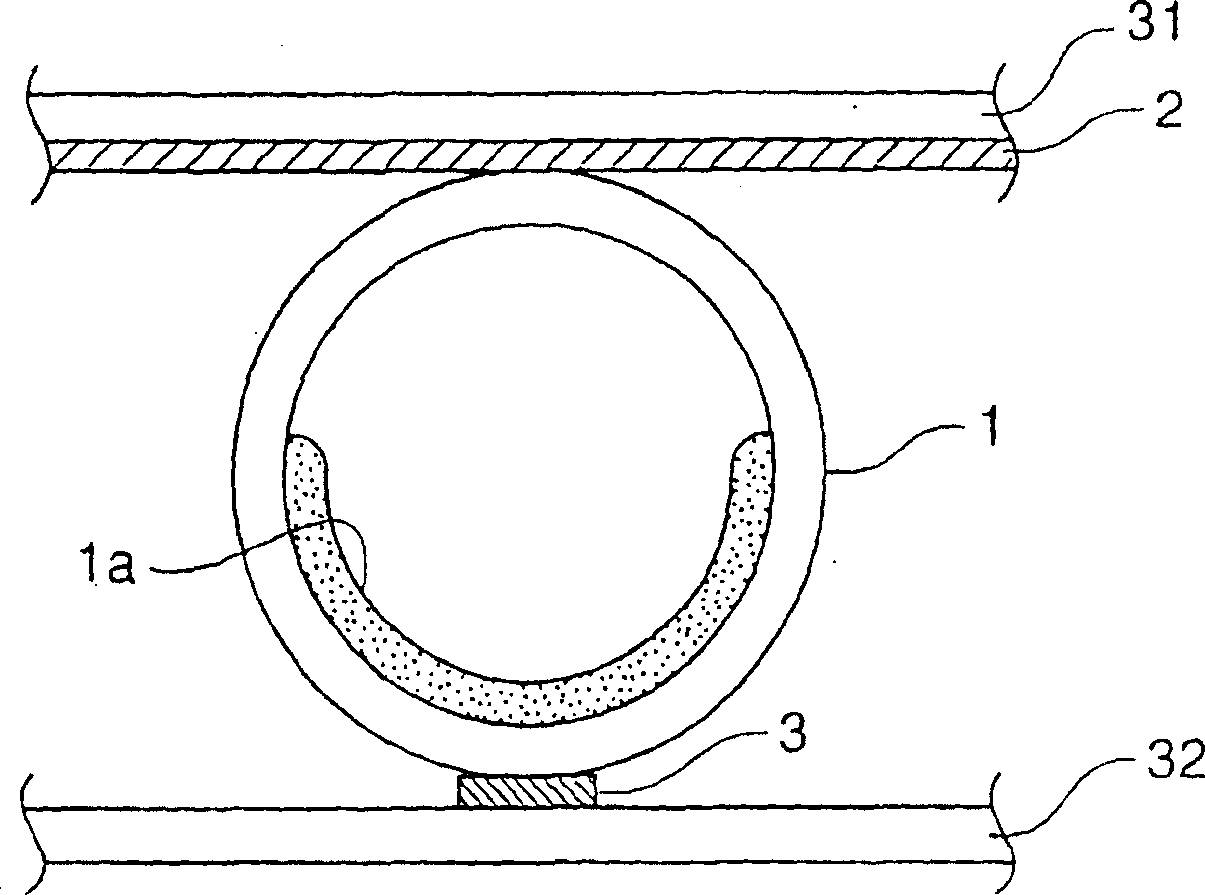
[0016] In the present invention, a luminous tube array can be used. The luminous tube array is composed of a plurality of luminous tubes arranged in parallel, and includes narrow tubes, each of which is equipped with a fluorescent layer and filled with discharge gas. Various light-emitting tubes known in the art can be used as the light-emitting tubes of the above-mentioned light-emitting tube array. A narrow tube of any diameter may be used to form the luminous tube, but a narrow glass tube having a diameter of about 0.5 to 5 mm is preferably used to form the luminous tube. The narrow tube preferably has a circular cross section, but may have a flat oval cross section.

[0017] A flexible sheet can be used which can properly support the array of light emitting tubes and deform it along a direction perpendicular to the longitudinal direction of the light emitting tubes. The flexible foil preferably consists of a light permeable membrane. As a film used for such a film, a com...


PUM


Abstract

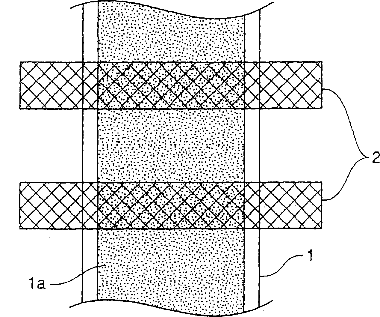
A light-emitting tube array display device includes a light-emitting tube array, a flexible sheet and a plurality of electrodes. The light-emitting tube array is constituted of a plurality of light-emitting tubes arranged in parallel. Each of the light-emitting tubes consists of narrow tube having a phosphor layer disposed and discharge gas filled inside. The flexible sheet is capable of flatly supporting the light-emitting tube array and deforming the light emitting tube array in a direction perpendicular to a longitudinal direction of the light-emitting tubes. The plurality of electrodes are formed on a face of the flexible sheet opposed to the light-emitting tubes, which are capable of generating discharge inside the light-emitting tubes by an application of voltage. Each of the electrodes is formed of a metal film having a mesh pattern, a ladder pattern, or a comb-shape pattern.

Description

technical field [0001] The present invention relates to a luminous tube array display device, in particular to a luminous tube array display device for displaying arbitrary images, wherein a plurality of luminous tubes (also called "picture tubes" or "gas discharge tubes") are arranged in parallel, and the luminous tubes The tube includes a narrow tube with a diameter of approximately 0.5 to 5 mm, which is provided with a fluorescent layer and filled with a discharge gas inside. Background technique [0002] As for the above-mentioned display device, such a display device is described in, for example, Japanese Unexamined Patent Publication No. 2000315460. In such a display device, a plurality of light-emitting points are formed in the longitudinal direction of the light-emitting tube by, for example, forming a plurality of electrodes on a substrate supporting the light-emitting tube, bringing the electrode-forming surface of the substrate into contact with the light-emitting...

Claims


Application Information

Patent Timeline
Patent Type & Authority Patents(China)
IPC IPC(8): H01J17/49H01J17/04G09F9/313H01J61/94G09F9/30H01J1/62H01J11/12H01J11/14H01J11/18H01J11/24H01J11/26H01J11/34H01J61/00H01J65/00
CPCH01J11/18H01J11/24H01J2211/245
Inventor 山田斉渡海章石本学中澤明粟本健司篠田傅
Owner SHINODA PLASMA
Learn More