Supercharge Your Innovation With Domain-Expert AI Agents!

Method and system for determining wavelength of light transmitted through optical fiber

A technology of optical fiber and wavelength, applied in the field of measuring the wavelength and system of light transmitted by optical fiber

Inactive Publication Date: 2001-07-25
INTELLIGENT OPTICAL SYST
View PDF0 Cites 3 Cited by
  • Summary
  • Abstract
  • Description
  • Claims
  • Application Information

AI Technical Summary

Problems solved by technology

However, the range of wavelengths that can correspond to a half period of the sinusoidal transfer function is also limited by the physics behind the construction of the dispersive coupler

Method used


Image

  • Method and system for determining wavelength of light transmitted through optical fiber
  • Method and system for determining wavelength of light transmitted through optical fiber
  • Method and system for determining wavelength of light transmitted through optical fiber

Examples


Embodiment Construction

[0025] Detailed Description of Preferred Embodiments

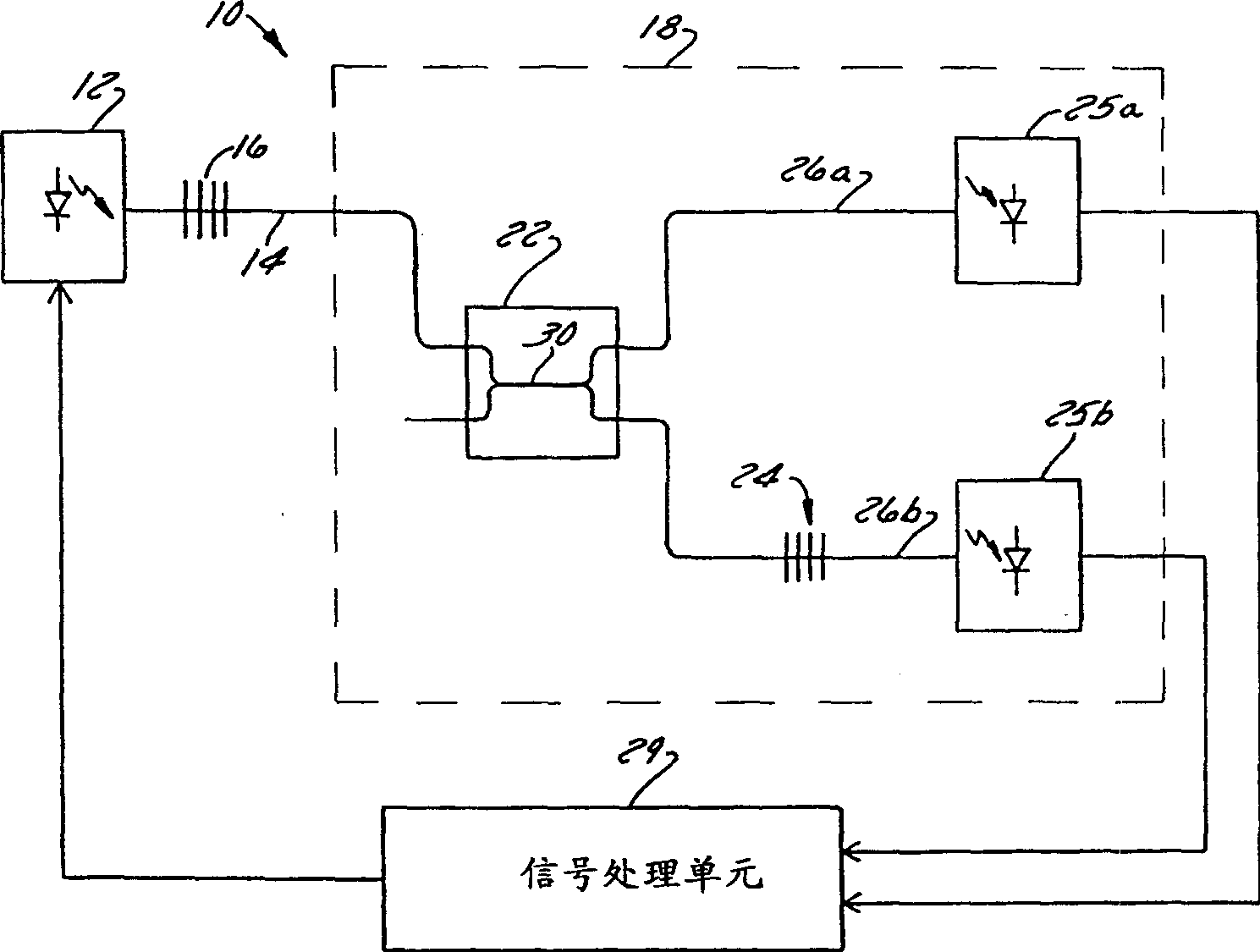
[0026] see now figure 1 , which is a schematic diagram of a system 10 for determining the average wavelength of light transmitted through an optical fiber. The system 10 includes an illumination source 12, an optical fiber 14, a sensor 16 arranged along the path of the optical fiber 14, a detector 18 connected to the far end of the optical fiber 14, and an output for controlling the illumination source 12 and processing the detector 18. Signal processing unit 29 of the signal. The signal processing unit 29 uses the output signal of the detector 18 to measure the average wavelength of the light output from the optical fiber 14 . For example, the signal processing unit 29 can be a computer, a digital signal processor, an analog signal processor, or any other suitable signal processing unit. Also, as previously indicated, the signal processing unit is generally used to measure any wavelength (not necessari...


PUM


Abstract

A method of determining the wavelength of light (12) transmitted in an optical fiber (14) comprises the steps of filtering the light using a filter (24), and then detecting (25a, 25b) the filtered light, and then determining the wavelength of the filtered light. The filter comprises a fiber grating (24) which is recorded in a portion of the optical fiber (14).

Description

Background of the invention [0001] 1. field of invention [0002] This invention relates to methods and systems for determining the wavelength of light transmitted by an optical fiber. In a particularly preferred embodiment, the present invention also relates to methods and systems for determining the wavelength of light transmitted by an optical fiber comprising a fiber grating having a variably modulated refractive index. [0003] 2. Related technology introduction [0004] It is often beneficial to be able to determine the wavelength of light transmitted by an optical fiber. Many types of fiber optic sensors are known which vary their transmission coefficients according to the parameter to be detected. For example, fiber optic Bragg grating temperature and pressure sensors are known that are generally transmissive, but also reflect a wavelength of light that changes in response to the temperature or pressure sensed by the sensor. An indication of the temperature or pr...

Claims


Application Information

Patent Timeline
Patent Type & Authority Applications(China)
IPC IPC(8): G01B9/02G01D5/353
CPCG01D5/353G01D5/35316G01D5/35335
Inventor 约翰·D·普罗哈斯卡洛萨·U·肯普罗伯特·A·利伯曼
Owner INTELLIGENT OPTICAL SYST
Features
  • R&D
  • Intellectual Property
  • Life Sciences
  • Materials
  • Tech Scout
  • Unparalleled Data Quality
  • Higher Quality Content
  • 60% Fewer Hallucinations
Learn More