
Hole punching device

A technology of punching device and hole position, which is applied in metal processing and other directions, and can solve problems such as deformation and shortening of service life

Inactive Publication Date: 2007-03-21
YUDONG PLASMA TECH
View PDF4 Cites 0 Cited by
  • Summary
  • Abstract
  • Description
  • Claims
  • Application Information

AI Technical Summary

Problems solved by technology

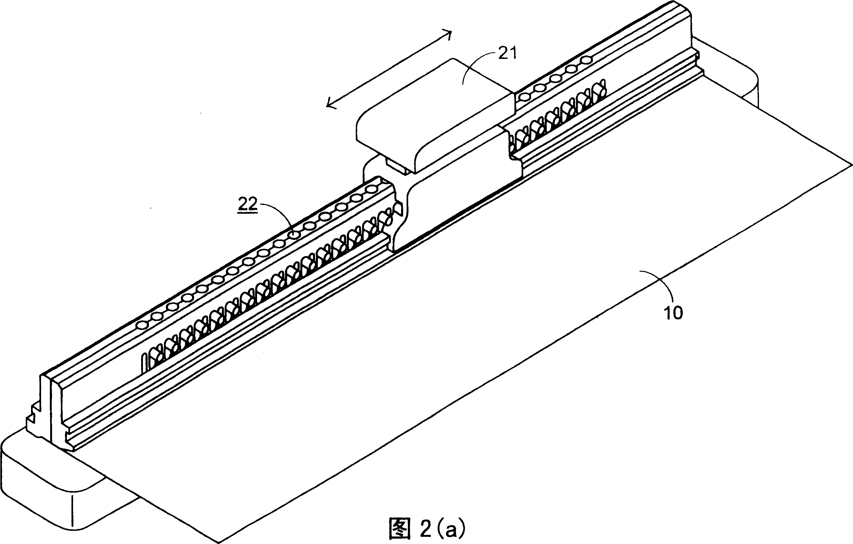
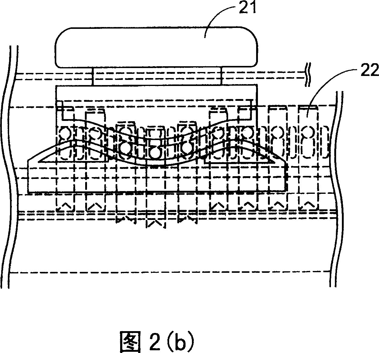
[0004] Referring again to Fig. 2(b) and Fig. 2(c), it is a schematic diagram of the local structure of the sliding handle 21 and the cutting tool 22, which clearly shows that there are actuating needle structures 220 on both sides of the main body of the cutting tool 22. , and the sliding groove structure 210 on the sliding handle 21 is slidably fitted to the actuating needle structure 220, and the cutting tool 22 is pushed downwards by the pushing force applied by the sliding groove structure 210 to the actuating needle structure 220 for punching. Hole operation, so the connection between the actuating needle structure 220 and the main body of the cutting tool 22 will bear the pressure of great force, which will easily cause deformation therebetween and shorten the service life. How to improve the lack of these commonly used devices is for Main purpose of developing the present invention

Method used


Image

  • Hole punching device
  • Hole punching device
  • Hole punching device

Examples


Embodiment Construction

[0035] Please refer to Fig. 3(a) and Fig. 3(b), which are schematic diagrams of the structure of the first preferred embodiment developed by the present invention to improve the lack of commonly used punching devices. It is a punching device used in In the punching operation of a sheet (such as common paper), the punching device is mainly composed of a slide rail main body 30, a plurality of cutting knives 31 and a sliding assembly 32, wherein the slide rail main body 30 has two sides Wall 301, an accommodating space 302 is formed between the two side walls 301, the cutting tool 31 is placed in the accommodating space 302, and the top of the tool body 311 of each cutting tool 31 can abut against the sliding assembly 32, And each side of cutter main body 311 is fixedly connected with a guide cross column 310, and this guide cross column 310 passes through the corresponding guide groove 3010 on the side wall 301, makes this cutting tool 31 can carry out an initial position and al...


PUM


Abstract

The puncher for punching hole in a sheet includes one sliding track with one holding space; several cutting tools set in the holding space; and one sliding assembly driven by the user to slide on the sliding track and push downward the tops of the cutting tools for punching hole in the sheet. The present invention has greatly reduced force onto the puncher and prolonged service life of the puncher.

Description

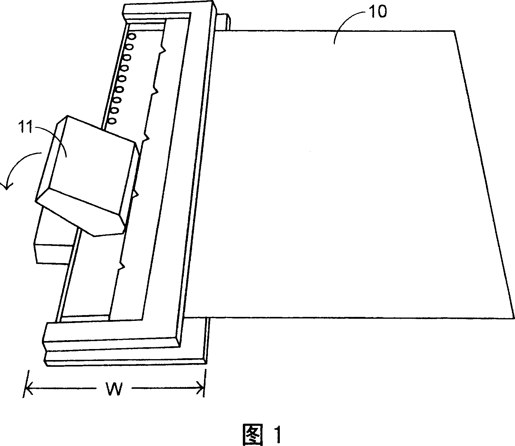
technical field [0001] The invention relates to a punching device, in particular to a punching device applied to the punching operation of sheet objects. Background technique [0002] Please refer to FIG. 1 , which is a schematic diagram of the appearance structure of a traditional paper punching device, which mainly provides the user with pressing the handle 11 to punch the paper 10. As can be seen from the structure in the figure, the user needs to press the handle 11 with great force. Press down the handle 11 in the direction of the arrow in the figure to complete the drilling operation of multiple holes at one time, but because the production of multiple holes is completed at one time, it is inevitable that there will be more laborious problems, and this common device also has a wide W is a big disadvantage. [0003] In order to improve the problems that the commonly used punching devices are too laborious and bulky, the punching device disclosed in U.S. Patent No. 5,46...

Claims


Application Information

Patent Timeline
Patent Type & Authority Patents(China)
IPC IPC(8): B26F1/04B26D5/08B26D5/10
Inventor 李培源
Owner YUDONG PLASMA TECH
Learn More