Lens moving mechanism

A lens moving and lens holding technology, applied in electromechanical devices, applications, coatings, etc., can solve problems such as difficulty in predicting the moving and positioning accuracy of the lens holding body, easy loosening of the lens holding body, and reducing the moving and positioning accuracy of the lens holding body. , to achieve the effect of improving the accuracy of mobile positioning

Inactive Publication Date: 2007-03-28
ALPS ALPINE CO LTD
View PDF5 Cites 0 Cited by
  • Summary
  • Abstract
  • Description
  • Claims
  • Application Information

AI Technical Summary

Problems solved by technology

[0005] In the above-mentioned prior art, the lens holder is moved along the optical axis through the screw fit of the first threaded part of the support body and the second threaded part of the lens holder. The gap between the parts, and the lens holder is prone to loosening (deflection) when moving in the direction of the optical axis
Therefore, there is a problem that it is difficult to predict the movement positioning accuracy of the lens holder in the direction of the optical axis.
Thereby, the above-mentioned problem is looked at from other point of view, can worry about reducing the movement positioning accuracy of lens holder in the optical axis direction.

Method used


Image

  • Lens moving mechanism
  • Lens moving mechanism
  • Lens moving mechanism

Examples


Embodiment Construction

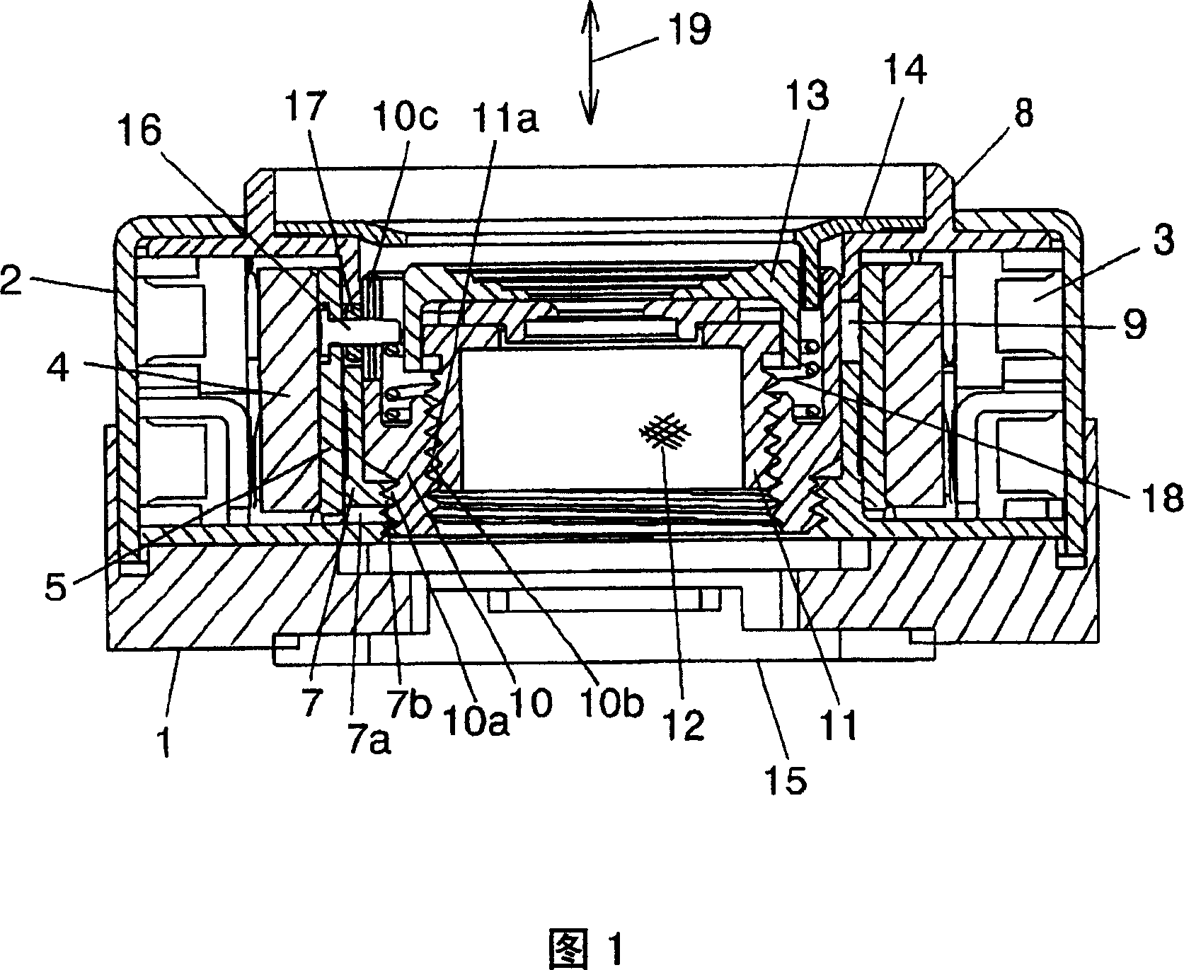
[0030] Next, the best mode for implementing the lens moving mechanism of the present invention will be described with reference to the drawings.

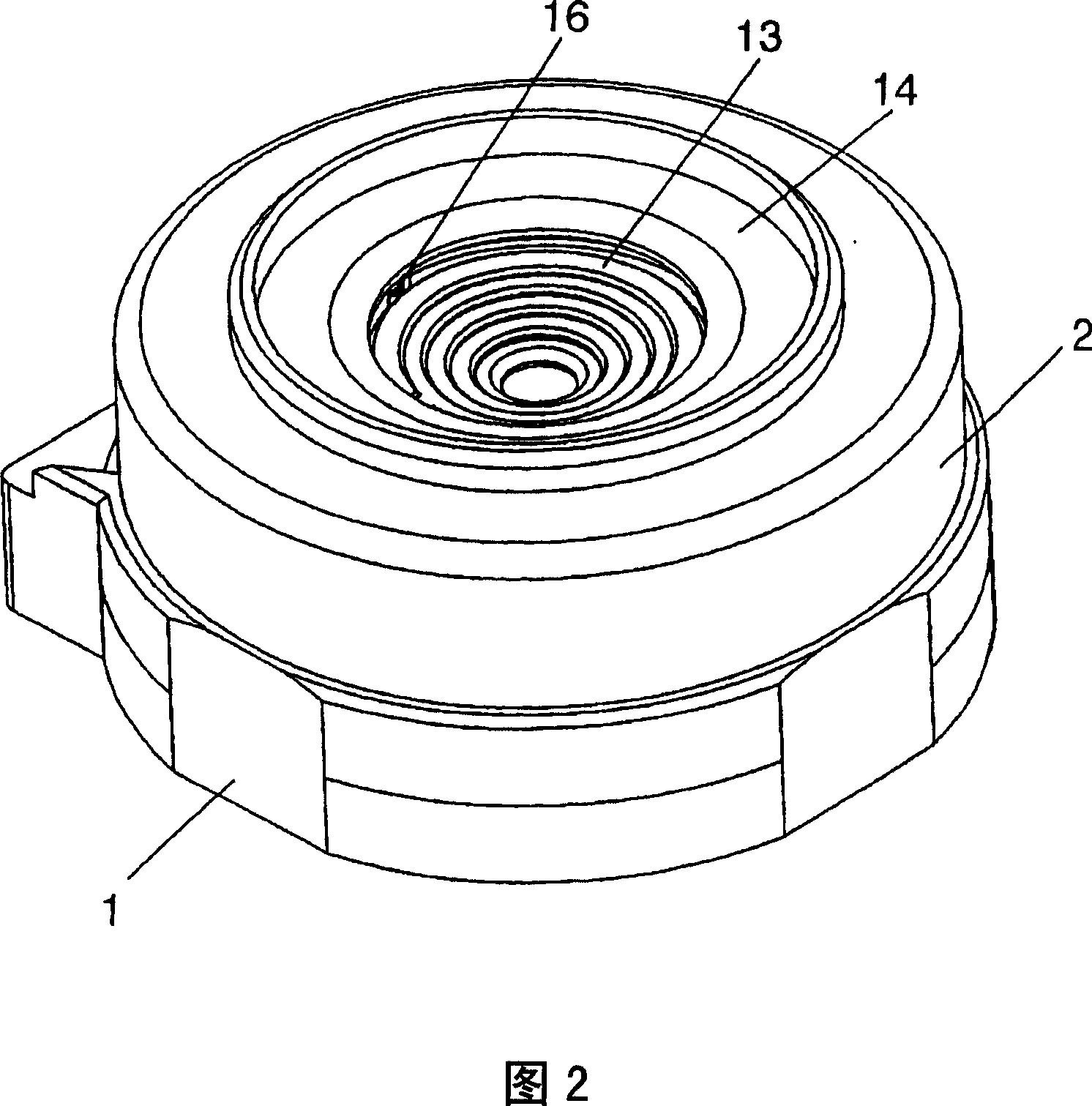
[0031] FIG. 1 is a longitudinal sectional view showing a first embodiment of a lens moving mechanism of the present invention, and FIG. 2 is a perspective view showing an appearance of the first embodiment shown in FIG. 1 .

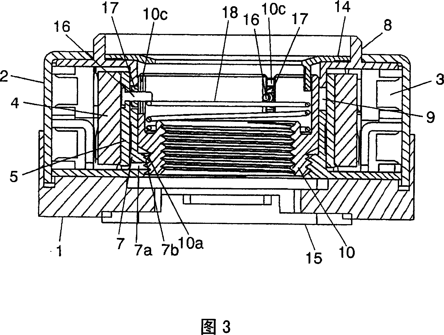
[0032] 3 is a longitudinal sectional view showing a state where a lens cover, a lens barrel, and a lens are removed from the first embodiment shown in FIG. 1 . 4 is a perspective view showing a state where the stopper plate and lens cover are removed from the first embodiment shown in FIG. A perspective view of the state of the barrel and lens. 6 is a perspective view showing the assembly relationship of the lower guide body, the rotor yoke, the guide pin, the roller member, the cage and the spring member included in the first embodiment shown in FIGS. 2 is a perspective view showing the assembly relationship...


PUM


Abstract

The invention aims to provide a lens moving mechanism capable of eliminating backlash between the 1st screw part of a supporting body and the 2nd screw part of a lens holding body screwed with the 1st screw part. The lens moving mechanism is equipped with a lower guide 7 supporting a rotor member including a cylindrical magnet 4 and a rotor yoke 5, arranged inside the rotor yoke 5 and having the 1st screw part 7b, and a holder 10 arranged inside the guide 7 and having the 2nd screw part 10a screwed with the 1st screw part 7b, and the yoke 5 has a guide pin 16 rotating the holder 10. Then, it is equipped with a spring member 18 energizing the guide pin 16 and the holder 10.

Description

technical field [0001] The present invention relates to a lens moving mechanism that rotates a lens holding body that holds a lens and moves it in an optical axis direction driven by a motor. Background technique [0002] Patent Document 1 shows such a prior art. This prior art is provided with a rotor member driven by a motor to rotate, a support body that supports the motor including the rotor member and has a first threaded portion on the inner periphery, and a support body that is arranged inside the support body, holds a lens, and has a threaded portion on the outer periphery. A lens holder with a second threaded portion threaded with the first threaded portion of the support. The rotor member described above has an engaging portion for rotating the lens holder. The engaging portion is constituted by a protruding piece that comes into contact with a groove portion formed on the peripheral portion of the lens holder. [0003] In this prior art, when the rotor member i...

Claims


Application Information

Patent Timeline
Patent Type & Authority Patents(China)
IPC IPC(8): G02B7/02H02K37/00G02B7/04
CPCG02B7/04G03B3/10G03B5/04G02B7/022G02B7/026H02N2/006H02N2/02
Inventor 龟山泰明
Owner ALPS ALPINE CO LTD
Why Eureka
Try Eureka