Multipath clock detecting device

A clock detection and clock technology, applied in the field of communication, can solve the problem of high cost, reduce the cost of the circuit, and avoid the effect of being difficult to obtain.

Active Publication Date: 2007-04-04
ZTE CORP
View PDF4 Cites 0 Cited by
  • Summary
  • Abstract
  • Description
  • Claims
  • Application Information

AI Technical Summary

Problems solved by technology

In this way, when the measured clock frequency is high, the selection of detection frequency becomes the bottleneck of circuit implementation, and the cost of implementation is also very high.

Method used


Image

  • Multipath clock detecting device
  • Multipath clock detecting device
  • Multipath clock detecting device

Examples


Embodiment Construction

[0014] The present invention will be further described in detail below in conjunction with the accompanying drawings and embodiments.

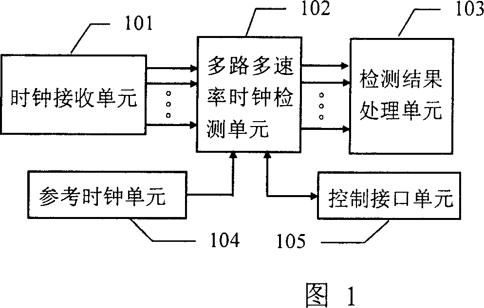
[0015] Fig. 1 is the schematic structural diagram of the detection device proposed by the present invention, as shown in Fig. 1, the multi-channel clock detection device proposed by the present invention includes a clock receiving unit 101, a multi-channel multi-rate clock detection unit 102, and a detection result processing unit 103 , refer to the clock unit 104 and the control interface unit 105; the clock receiving unit 101 is used to receive the clock signal under test and perform level interface and voltage amplitude conversion on the clock signal under test; the detection result processing unit 103 is used to complete the detection Latching, output and indication of the result; the reference clock unit 104 provides a reference clock signal output to the multi-channel multi-rate clock detection unit 102; the control interface unit 105 is ...


PUM


Abstract

The invention discloses a multi-path clock detester which comprises: a clock receiving unit, a multi-path multi-speed clock detecting unit, a detecting result processing unit, a reference clock unit and a control interface unit, wherein the reference clock unit is used to receive the detected clock signal and change the level interface and the voltage breadth of the detected signal; the detecting result processing unit is used to finish the lock, output and indicate of the detecting result; the reference clock unit is used to provide a reference clock signal to the multi-path multi-speed clock detecting unit; the control interface unit is used to generate the corresponding break signal to the upper position controller and receive the control of the upper position controller to finish the reset and disinfect of the multi-path multi-speed clock detecting unit; the multi-path multi-speed clock detecting unit is formed by a plurality of clock detecting circuits to finish the detect of the multi-path detecting clock with different speed.

Description

technical field [0001] The invention relates to clock testing in the communication field, in particular to a device for realizing multi-channel multi-rate clock detection. Background technique [0002] In the telecommunication system, the clock units or clock boards of many systems will output multiple clocks of different rates to other systems and single boards. When testing these systems, the existence status and performance indicators of the output clocks are usually Items that must be tested. On the other hand, sometimes the clock in the communication system is temporarily lost (temporary loss of the clock is manifested as a single high level or low level of the clock signal). In many applications, once the clock is lost, it will affect the entire system It will have a serious impact, so the clock must be monitored in real time. [0003] In the implementation of conventional technology, a monostable trigger (such as 74HC123, etc.) can be used to detect the pulse loss o...

Claims


Application Information

Patent Timeline
Patent Type & Authority Patents(China)
IPC IPC(8): H03K21/40
Inventor 李刚健朱红军汪承研周嵘朱堃
Owner ZTE CORP
Why Eureka
Try Eureka