
Method and apparatus for improved ion bunching in an ion implantation system

A technology of ion clustering, applied in the direction of irradiation device, electric/magnetic device to deflect/concentrate/focus the beam, discharge tube, etc., can solve the problems of ion loss and spending more time

Inactive Publication Date: 2007-04-11
AXCELIS TECHNOLOGIES
View PDF3 Cites 0 Cited by
  • Summary
  • Abstract
  • Description
  • Claims
  • Application Information

AI Technical Summary

Problems solved by technology

In conventional systems, perhaps around 80% of the ions generated by the ion source are lost (e.g., do not reach the workpiece), thus taking more time to complete the required implant

Method used


Image

  • Method and apparatus for improved ion bunching in an ion implantation system
  • Method and apparatus for improved ion bunching in an ion implantation system
  • Method and apparatus for improved ion bunching in an ion implantation system

Examples


Embodiment Construction

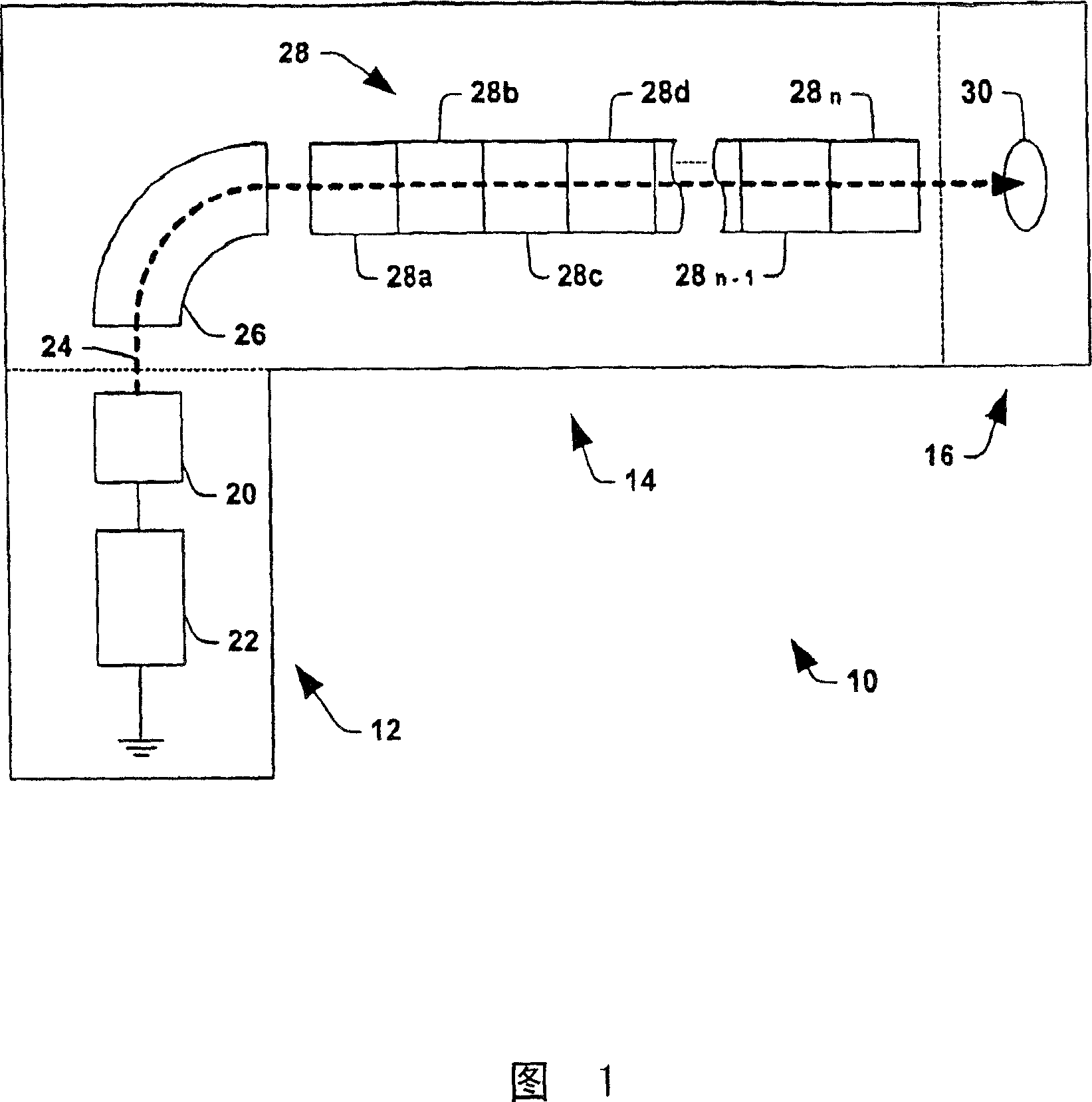
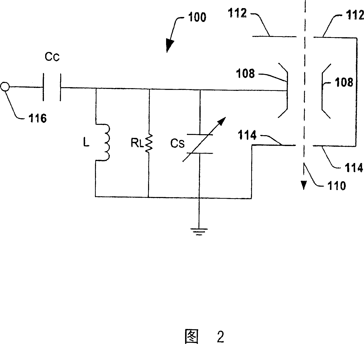
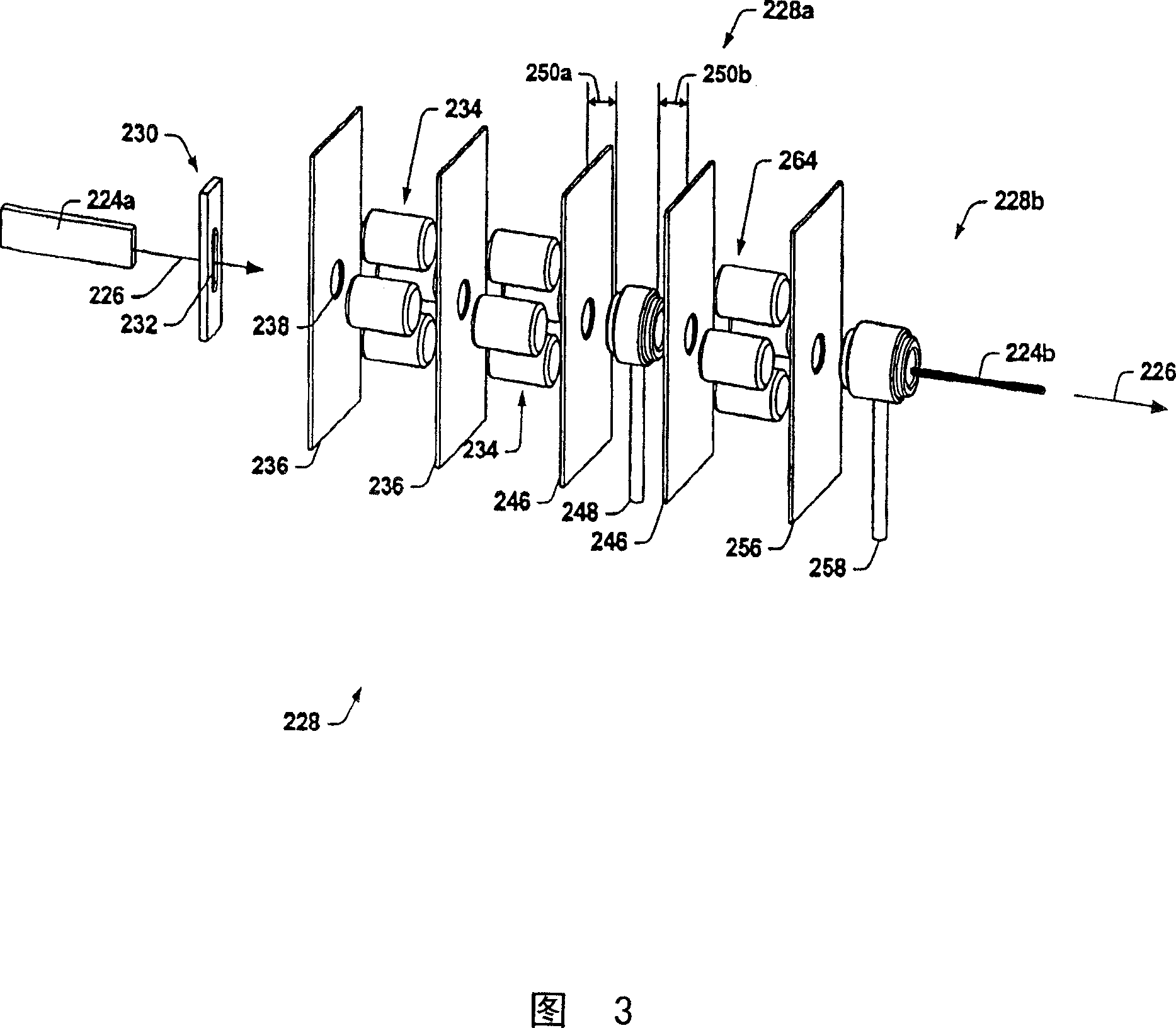
[0022] The invention will now be described with reference to the drawings, in which like reference numerals refer to like elements throughout. An ion clusterer stage is dedicated to the ion clustering of the ion implantation system. The ion clusterer stage can be placed upstream of an accelerating stage in a linac to cluster or agglomerate ions therein, thereby reducing ion losses from the linac. This clusterer stage can operate at lower energies than subsequent acceleration stages and can also be provided with a drift region to aid ion clustering. The present invention also includes an asymmetric double-gap clusterer stage and a slot clusterer stage to further improve ion implantation efficiency. Various methods of accelerating ions within the linear accelerator of an ion implanter will also be described later.

[0023]In order to understand the context of the various features of the present invention, a brief discussion will now be given of the general interconnections bet...


PUM


Abstract

An ion buncher stage for a linear accelerator system is disclosed for bunching ions in an ion implantation system. The ion buncher stage may be employed upstream of one or more linear accelerator stages such that the loss of ions in the linear accelerator system is reduced. The invention further includes an asymmetrical double gap buncher stage, as well as a slit buncher stage for further improvement of ion implantation efficiency. Also disclosed are methods for accelerating ions in an ion implanter linear accelerator.

Description

technical field [0001] This invention relates generally to ion implantation systems and, more particularly, to methods and apparatus for improving ion clustering in ion implantation systems. Background technique [0002] In the manufacture of semiconductor devices, ion implantation is used to incorporate impurities into semiconductors. A high energy (HE) ion implanter is described in US Patent 4,667,111, assigned to the assignee of the present invention, and incorporated herein by reference in its entirety. This high-energy ion implanter is used for deep implantation of substrates to produce, for example, some inverted wells. For such deep implants, an implant energy of 1.5 MeV (million electron volts) is typical. Typical implant energies for this type of injector are at least between 300KeV and 700KeV, although lower energies can be used. Certain high-energy ion implanters can deliver ion beams with energies up to 5 MeV. [0003] Referring to FIG. 1 , a typical high ene...

Claims


Application Information

Patent Timeline
IPC IPC(8): H01J37/317H05H7/18G21K1/08G21K5/04
CPCH01J2237/04737H05H7/18H01J37/3171
Inventor K·萨亚达特曼德W·迪维吉里奥
Owner AXCELIS TECHNOLOGIES
Learn More