Pick-up device
A pick-up device and communication hole technology, applied in the direction of protecting the transducing head, optical recording head, reducing the physical parameters of the carrier, etc., can solve the problem of insufficient heat dissipation, etc.
- Summary
- Abstract
- Description
- Claims
- Application Information
AI Technical Summary
Problems solved by technology
Method used
Image

Examples
no. 1 Embodiment
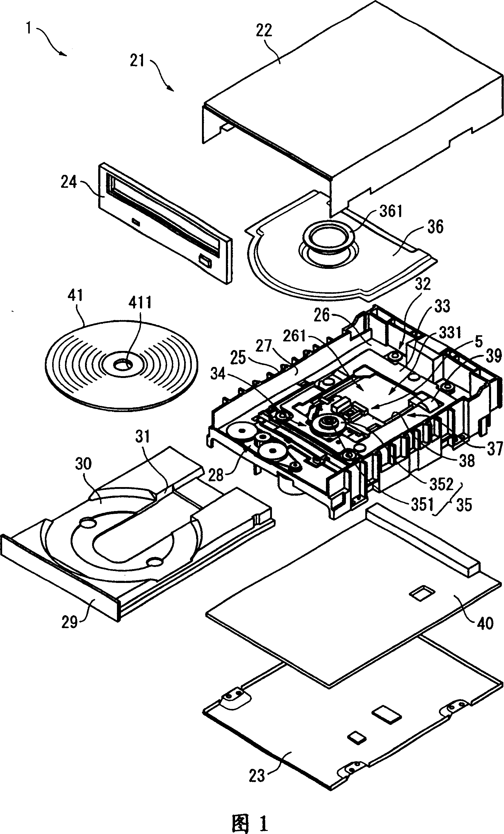
[0023] Fig. 1 is an exploded perspective view of a disc device having a pickup device according to a first embodiment of the present invention, and reproducing information recorded on or recording information on an optical disc such as a DVD or a CD.
[0024] This disc device 1 is constituted by: having an outer case 21, an inner case 25 provided inside the outer case 21, a disc holder 29 for placing an optical disc 41 as an optical recording medium, which can advance and retreat on the inner case 25, The main body 32 for reproducing or recording information on the optical disc 41 and the circuit board 40 having electronic components for controlling the operation of the main body 32 are provided in the inner case 25 .
[0025] The outer casing 21 is constituted as follows: an upper casing 22 with openings on the lower side and the front side in FIG. It is a flat cuboid shape.
[0026] The inner case 25 has a bottom surface 26 having a hole 261 in the approximate center and a ...
no. 2 Embodiment
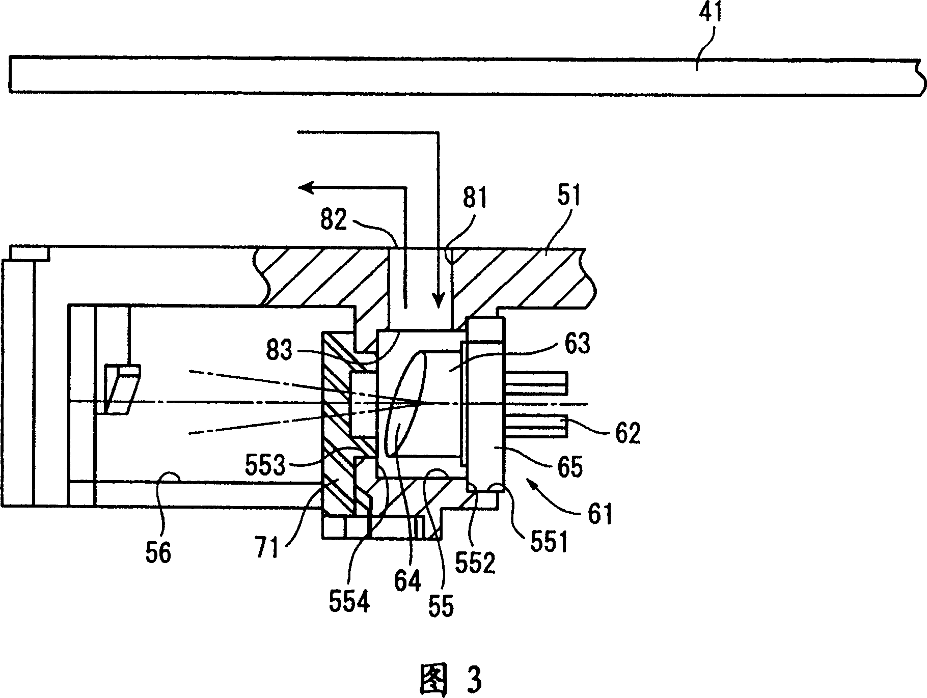
[0070] A second embodiment of the present invention is shown in FIG. 4 . Although the basic configuration of the second embodiment is the same as that of the first embodiment, the difference between the second embodiment and the first embodiment lies in that the heat radiation passage 81 as a heat radiation mechanism is provided coaxially with the communicating hole 55 interposed therebetween. two.
[0071] That is, as the heat dissipation passage 81 , a first heat dissipation passage 811 provided through the upper wall surface of the communication hole 55 and a second heat dissipation passage 812 provided through the lower wall surface of the communication hole 55 are provided. The mutual central axes of the first heat dissipation passage 811 and the second heat dissipation passage 812 are substantially on the same straight line.
[0072] According to this constitution, in addition to the effects (1) to (7) of the first embodiment described above, the following effects can b...
no. 3 Embodiment
[0077] A third embodiment of the present invention is shown in FIG. 5 . Although the basic structure of the third embodiment is the same as that of the first embodiment, the difference between the third embodiment and the first embodiment is that an air flow receiving member 84 is provided on the heat radiation passage 81 as a heat radiation mechanism.
[0078] That is, an airflow receiving member 84 having a wall surface facing the airflow generated by the rotation of the optical disc 41 is provided on the edge of the outer opening 82 of the heat dissipation path 81 .
[0079] The wall surface facing the air flow is a plane, and is parallel to the axis of the heat dissipation path 81 .
[0080] The airflow receiving member 84 is integrally formed upright from the pick-up base 51 .
[0081] According to this constitution, in addition to the effects (1) to (7) of the foregoing embodiments, the following effects can be obtained.
[0082] (9) An air flow receiving member 84 hav...
PUM
 Abstract
Description
Claims
Application Information
 - R&D
- Intellectual Property
- Life Sciences
- Materials
- Tech Scout
- Unparalleled Data Quality
- Higher Quality Content
- 60% Fewer Hallucinations
Browse by: Latest US Patents, China's latest patents, Technical Efficacy Thesaurus, Application Domain, Technology Topic, Popular Technical Reports.
© 2025 PatSnap. All rights reserved.Legal|Privacy policy|Modern Slavery Act Transparency Statement|Sitemap|About US| Contact US: help@patsnap.com