Supercharge Your Innovation With Domain-Expert AI Agents!

Thin battery and method for manufacturing same

A battery, thin technology, applied in the direction of small flat battery/battery, small size battery/battery pack, large size battery/battery pack, etc., can solve problems such as expansion, and achieve the effect of preventing the increase of resistance

Inactive Publication Date: 2007-05-16
GS YUASA INT LTD
View PDF6 Cites 0 Cited by
  • Summary
  • Abstract
  • Description
  • Claims
  • Application Information

AI Technical Summary

Problems solved by technology

As a result, in the case where the battery is placed in a high-temperature environment, a large amount of gas generated due to pre-charging will expand, which may cause problems similar to those described above

Method used


Image

  • Thin battery and method for manufacturing same
  • Thin battery and method for manufacturing same
  • Thin battery and method for manufacturing same

Examples


Embodiment approach 1

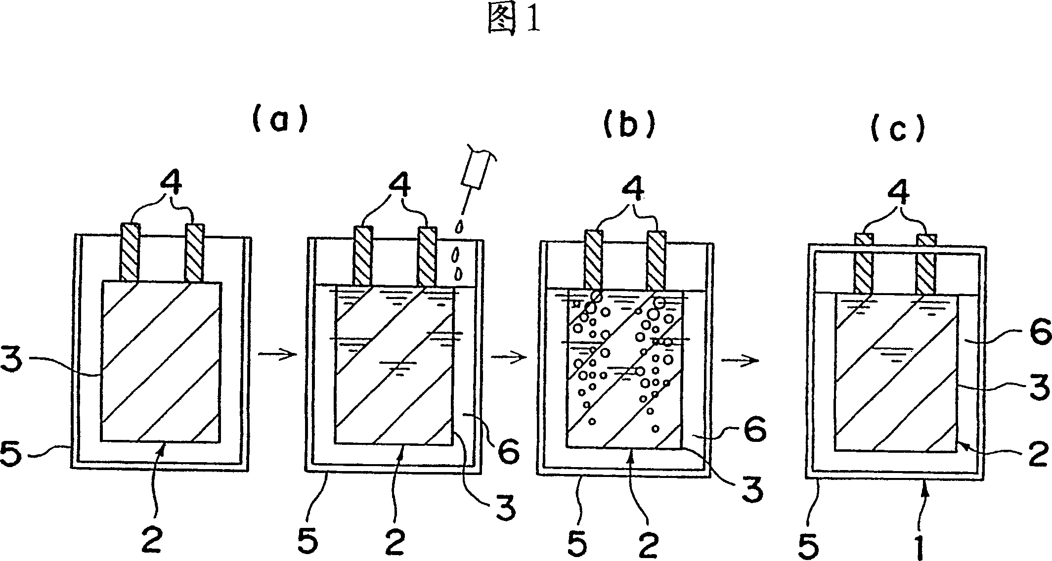
[0026] The electrolyte is a mixed electrolyte made by mixing ethylene carbonate (EC) and dimethyl carbonate (DMC) (volume ratio: EC:DMC=4:6), and then inject the mixed electrolyte through the separator and In negatively bonded battery bodies, the process takes place at low pressure. After precharging, the pressure in the vacuum chamber is reduced to 8.01 kPa at room temperature, which is just three times the vapor pressure of the mixed electrolyte solution of 2.67 kPa, and the casing 10 is sealed. The size of the lithium ion battery thus produced was 130 mm x 60 mm x 4 mm. After the pressure is restored to atmospheric pressure and placed for a specified time, put the entire battery into a flowing paraffin solution, and the casing is unsealed, then collect the gas released from the battery at this time, measure its volume, and use the measured volume as the remaining in the casing volume of gas. Then, it was stored at 85° C. for 24 hours, and the battery thickness increase du...

Embodiment approach 2

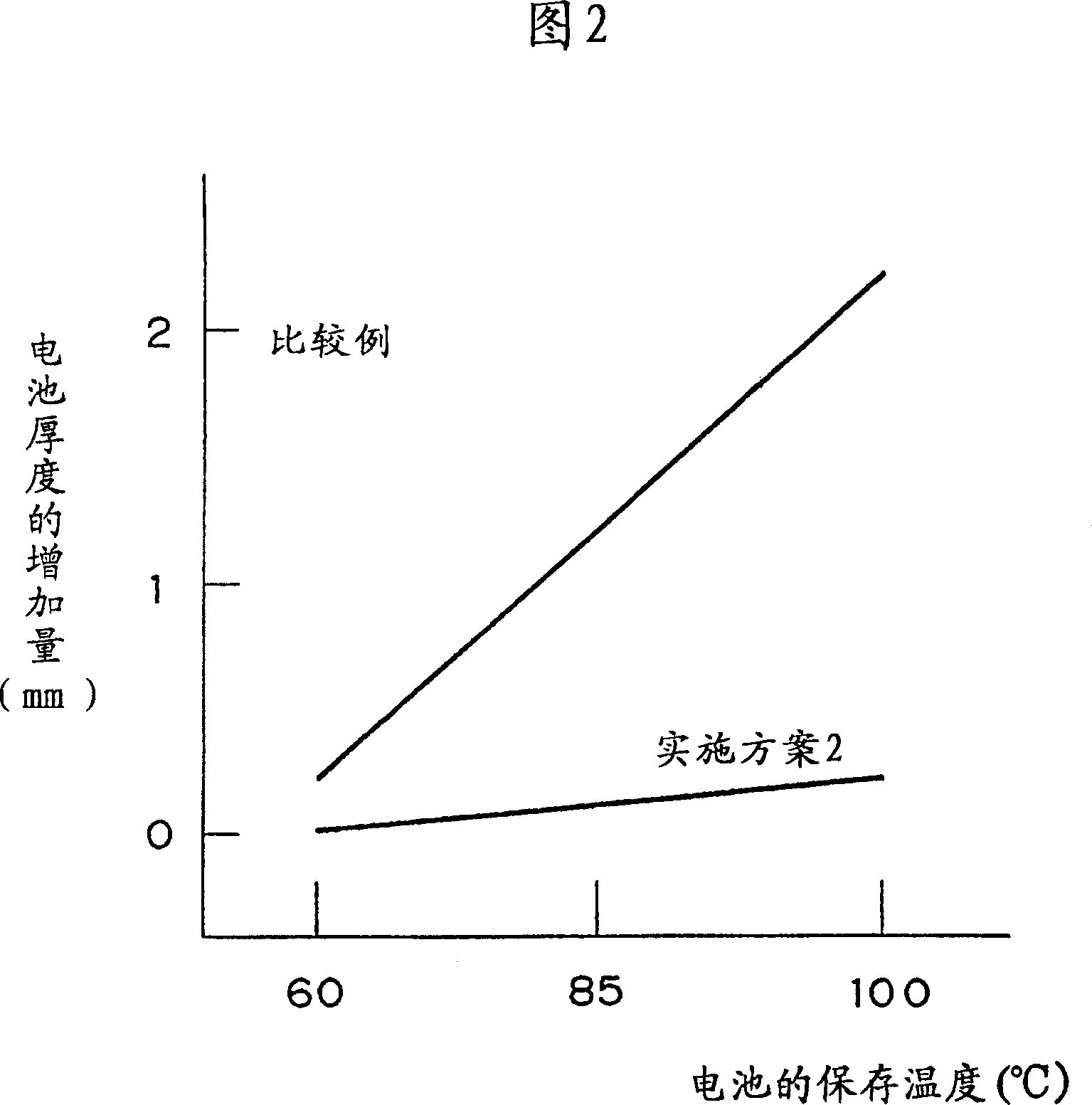
[0028]The electrolyte adopts the mixed electrolyte made by mixing ethylene carbonate (EC) and dimethyl carbonate (DMC) (volume ratio is EC:DMC=3:7), except at room temperature, the pressure of 4.02kPa (that is, mixing Electrolyte solution vapor pressure 1.34kPa 3 times) outside sealing, prepare lithium-ion secondary battery with the same method as embodiment 1, and battery is preserved at 85 ℃ for 24 hours, measure the increase of battery thickness at this moment, the result is as follows Table 1 shows. The residual gas volume is reduced to 0.03ml. Since the vapor pressure of the electrolyte in the battery is reduced, the pressure during sealing can be further reduced, thereby reducing the residual gas volume. Even if the battery is placed in a high-temperature environment, its thickness will not increase by more than 0.1 mm, that is, the thickness will remain basically unchanged.

Embodiment approach 3

[0030] A lithium-ion secondary battery was prepared in the same manner as in Embodiment 2, except that it was sealed at a low pressure in a vacuum chamber with a pressure of 53.3 kPa. The battery was also stored at 85° C. for 24 hours, at which time the thickness of the battery increased and changed as shown in Table 1. In this embodiment, the thickness of the battery does not increase by more than 0.1 mm. In this embodiment, the sum of the pressure increase caused by the gas generated by the self-discharging reaction of the battery and the increase in the vapor pressure of the electrolyte will not exceed 48 kPa in total. It is generally believed that this is because the pressure has not yet reached the atmospheric pressure of 101.3 kPa.


PUM


Abstract

A battery body, which is composed of a laminated body obtained by laminating a cathode and an anode via a separator or a wound body obtained by winding them in a laminated structure and a plurality of leads connected to the cathode and the anode, is contained in a flexible package, and after an electrolyte solution is injected thereinto, an opening of the package is sealed at pressure which is lower than atmospheric pressure and is reduced to not less than vapor pressure of the electrolyte solution so that a thin battery is fabricated. A rise in pressure in the battery due to generation of gas in the battery and volume expansion of the gas can be restrained when the battery is maintained at high temperature.

Description

technical field [0001] The invention relates to a method for preparing a thin battery and a thin battery made by the method. Background technique [0002] In recent years, with the popularity of portable devices, such as notebook personal computers and mobile phones, the application of high-energy batteries represented by nickel-metal hydride secondary batteries and lithium-ion secondary batteries has been rapidly developed. Traditionally, for lithium batteries, the wound body obtained by winding the positive and negative electrode stacks through the separator is stored in a metal case, and the negative electrode, the separator, and the positive electrode are in close contact under the pressure of the case to ensure electrical connection. . However, due to the use of a metal case, there has been a problem that it is difficult to reduce the weight and thickness of the battery. [0003] In order to solve this problem, Japanese Patent Laid-Open No. 10-177865 etc. have propose...

Claims


Application Information

Patent Timeline
Patent Type & Authority Patents(China)
IPC IPC(8): H01M10/40H01M10/38H01M10/04H01M6/10H01M6/50H01M10/05H01M10/36H01M50/105H01M50/119H01M50/121H01M50/122H01M50/124H01M50/609
CPCH01M6/10H01M10/05H01M2/36H01M2/0207H01M10/0436H01M6/5072H01M2/0275Y10T29/4911Y02E60/10Y02P70/50H01M50/609H01M50/105H01M50/121H01M50/124H01M50/119H01M50/122
Inventor 吉冈省二漆畑广明塩田久荒金淳吉濑万希子相原茂竹村大吾西村隆吉田育弘广井治浜野浩司尾崎博规市村英男川口宪治森安雅治中出口真治村井道雄塚本寿
Owner GS YUASA INT LTD
Features
  • R&D
  • Intellectual Property
  • Life Sciences
  • Materials
  • Tech Scout
  • Unparalleled Data Quality
  • Higher Quality Content
  • 60% Fewer Hallucinations
Learn More