Step motor driving device and method
一种步进电机、驱动装置的技术,应用在电动发电机控制、电气元件、电气程序控制等方向,能够解决无法完全地消除振动和噪声等问题
- Summary
- Abstract
- Description
- Claims
- Application Information
AI Technical Summary
Problems solved by technology
Method used
Image

Examples
no. 1 example
[0067] The stepper motor driving device of the first embodiment of the present invention generates a reference signal whose waveform has no sharp change in level and which exhibits a current limit value. Here, a waveform whose level does not change sharply is a waveform represented by a continuous function. The level change of a waveform represented by a continuous function is smooth. For example, sine, triangle, and trapezoidal waveforms that slope up and down are all examples of this type, but neither staircase nor rectangular waveforms are.
[0068] The stepping motor drive device performs PWM (pulse width modulation) control on the coil current according to the current limit value indicated by the reference signal. In detail, the PWM control is performed using a current limiting method.
[0069] The stepping motor driving device is explained in detail below with reference to the accompanying drawings.
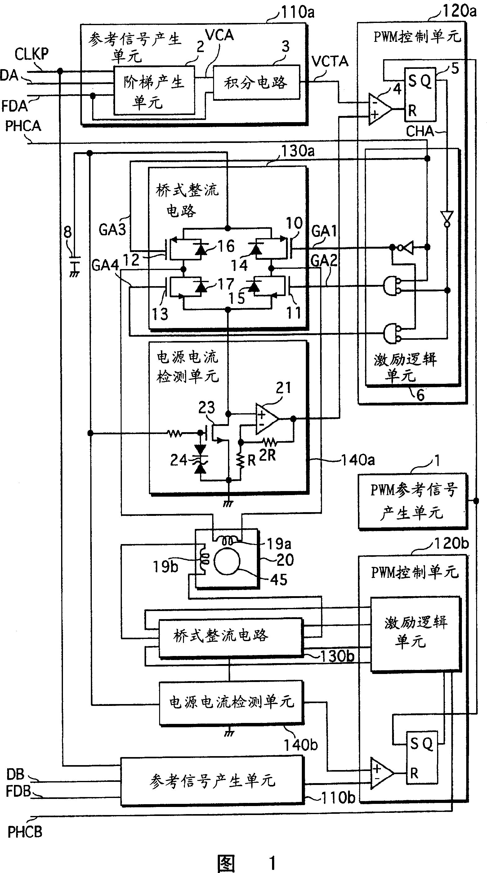
[0070] (the whole frame)
[0071] Figure 1 shows a functional bloc...
no. 2 example
[0105] The difference between the stepping motor driving device of the second embodiment of the present invention and the stepping motor driving device of the first embodiment lies in that, by identifying the pulse frequency of the clock signal CLKP among multiple pulse frequencies, gradation can be generated inside the device. frequency signal FDA, and using the generated graded frequency signal FDA to generate a reference signal VCTA. The following description mainly focuses on this point of difference from the first embodiment.
[0106] (Structure related to generation of reference signal VCTA)
[0107] Fig. 8 shows a functional block diagram of the structure related to the generation of the reference signal VCTA in the second embodiment. The difference between this structure and the first embodiment is that a pulse frequency identification unit 22 is added. The pulse frequency identification unit 22 generates the graded frequency signal FDA by identifying the pulse frequ...
no. 3 example
[0119] The difference between the stepping motor driving device of the third embodiment of the present invention and the second embodiment lies in the structure related to the generation of the reference signal VCTA. The following description mainly focuses on this point of difference from the second embodiment.
[0120] (Structure related to generation of reference signal VCTA)
[0121] Fig. 11 is a functional block diagram showing the structure related to the generation of the reference signal VCTA in the third embodiment. This structure differs from the second embodiment in that an integrating circuit 25 is included instead of the integrating circuit 3 .
[0122] (integrating circuit 25)
[0123] FIG. 12 is a functional block diagram showing a detailed structure of the integration circuit 25 . In the integration circuit 25, switches controlled by the graded frequency signal FDA and the program signal PRG are provided to adjust the resistance for determining the integrati...
PUM
 Abstract
Description
Claims
Application Information
 - R&D
- Intellectual Property
- Life Sciences
- Materials
- Tech Scout
- Unparalleled Data Quality
- Higher Quality Content
- 60% Fewer Hallucinations
Browse by: Latest US Patents, China's latest patents, Technical Efficacy Thesaurus, Application Domain, Technology Topic, Popular Technical Reports.
© 2025 PatSnap. All rights reserved.Legal|Privacy policy|Modern Slavery Act Transparency Statement|Sitemap|About US| Contact US: help@patsnap.com